WARNING! NEVER apply voltage or current to the meter that exceeds the specied
maximum stated.
WARNING! USE EXTREME CAUTION WHEN WORKING WITH HIGH VOLTAGES.
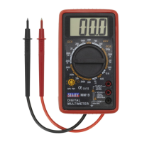
2. INTRODUCTION
High quality general-purpose multimeter with a large (46 x 25mm), clear and easy-to-read LCD display.
Supplied with test leads.
Measures:
- AC and DC Voltage
- DC Current
- Resistance
- Audible Continuity
- Diode/Transistor Verication Mode
3. SPECIFICATION
Model No: ...............................................................MM19.V3
AC Voltage (Accuracy):
............................. 200V, 750V (±2%)
DC Voltage (Accuracy):
............200mV, 2000mV, 20V, 200V (±1.5%), 1000V (±1.8%)
AC Current (Accuracy):
..................................................... No
DC Current (Accuracy):
....200µA, 2000µA, 20mA (±2%), 200mA (±2.2%), 10A (±2%)
Resistance (Accuracy):
............. 200Ω, 2000Ω, 20kΩ, 200kΩ (±1.8%), 2000kΩ (±2%)
Capacitance (Accuracy):
................................................... No
Temperature (Accuracy):
................................................... No
Frequency (Accuracy):
...................................................... No
Duty Cycle:
........................................................................ No
Continuity Audible:
........................................................... Yes
4. BATTERY INSTALLATION
WARNING! To avoid electric shock, disconnect the test leads from any source of voltage
before removing the battery cover.
4.2.1. Disconnect the test leads from the meter.
4.2.2. Open the battery cover by loosening the two cover screws using a cross head screwdriver.
4.2.3. Insert the battery into battery holder, observing the correct polarity.
4.2.4. Replace the battery cover. Secure with the screws.
WARNING! To avoid electric shock, do not operate the meter until the battery cover
is in place and fastened securely.
NOTE! If meter does not work properly, check the fuses and battery to make sure that
they are still good and that they are properly inserted.
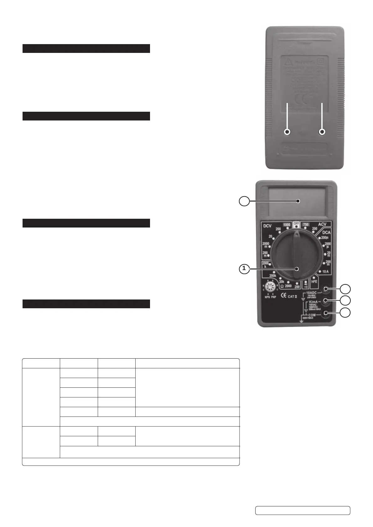
5. FEATURES
Refer to diagram on right hand side
1. Function Switch
2. LCD Display
3. Common Jack
4. V.Ω.mA Jack
5. 10A Jack
NOTE: Fuse and battery compartment are at the rear of the unit.
Original Language Version
© Jack Sealey Limited
REMOVE SCREWS
TO ACCESS
BATTERY AND
FUSES
1
2
3
4
5
SYMBOLS AND ANNUNCIATORS
•))) Continuity
Diode Test
Μ Micro (amps)
M Milli (volts, amps)
K Kilo (ohms)
Ω Ohms
DCV Volts Direct Current
ACV Volts Alternating Current
DCA Amps Direct Current
HFE Transistor Measurement
Function Range Resolution Accuracy
DC Voltage
(V DC)
200mV 100µV
±(1.5% reading + 2 digits)
2000mV 1mV
20V 10mV
200V 100mV
1000V 1V ±(1.8% reading + 2 digits)
OVERLOAD PROTECTION: 220Vrms AC for 200mV range and 1000VDC or 750Vrms AC for other
ranges.
AC Voltage
(V AC)
200V 100mV
±(2% reading + 2 digits
(50/60Hz)
750V 1V
OVERLOAD PROTECTION: 1000 V DC or 750Vrms AC for all ranges.
RESPONSE: Average responding, calibrated in rms of a sine wave.
FREQUENCY RANGE: 45Hz - 450Hz
MM19.V3 Issue:6 (H,F) 21/10/21
 Loading...