6.5.5. Maintain a safe distance from the battery whilst jump starting.
6.5.6. Turn on the ignition to start the vehicle.
NOTE: If the vehicle does not start after 4 to 5 seconds, allow the RoadStart unit to cool for 3 to 4 minutes, before attempting to
jump start the vehicle again. If this is not done, the unit could sustain damage.
DANGER OF EXPLOSION, WHICH COULD RESULT IN DAMAGE OR INJURY IF THE FOLLOWING INSTRUCTIONS ARE NOT
OBSERVED.
6.5.7. When the vehicle has started, disconnect the negative (-) black clamp (negative earthed vehicles) or red (+) positive (positive
earthed vehicles) within 15 seconds
6.5.8. Turn the rotary switch to OFF.
6.5.9. Disconnect the positive (+) red clamp negative earthed vehicles or black negative clamp (-) on positive earthed vehicles.
6.5.10. Return the clamps to the mounting bars at the back of the casing.
6.5.11. Rechargetheunitattherstavailableopportunity.
6.6. ALTERNATIVE VEHICLE POWER SUPPLY
6.6.1. When a vehicle battery is disconnected, the memory systems in radios, electronic ignition systems and alarms are frequently lost.
6.6.2. When replacing a battery the RoadStart unit can be used as an alternative power supply by connecting the units 12V DC extension
lead(g.8)intothecigarettelightersocket.ThiswillpreventlossofmemoryinthesystemsoutlinedinParagraph6.7.1.
R WARNING! The vehicle positive battery cable will be live and MUST be insulated (e.g. in a heavy duty plastic bag).
6.7. MULTIPURPOSE POWER SUPPLY
6.7.1. This RoadStart unit can be used as a multipurpose power supply to power up any equipment which can connect via a 12V DC
cigarette lighter plug. (17amp maximum).
6.7.2. Open the socket cover and plug in the lead from the appliance/accessory.
6.7.3. Activate the socket by moving the switch above it to the ON position. The appliance operating time will depend on the state
of charge of the battery and the amount of current drawn by the appliance. Periodically check the battery status. If only the red
light comes on recharge the unit as soon as possible.
6.7.4. The socket is protected by a circuit breaker which will trip if the current exceeds 17amps. After 15 to 20 minutes cooling time the
circuit breaker will automatically reset.
6.7.5. DO NOT plug a cigarette lighter into the socket on the unit.
6.8. USING THE WORKLIGHT
6.8.1. To turn the worklight ON and OFF use the switch on the left hand side of the lense. If used on its own the light will operate for up to
40 hours on a fully charged battery. Turn OFF light when not required to conserve battery power.
6.8.2. Thelightusesa12V3wattbulb.ToreplacethebulbrstlyensurethatthelightswitchisOFF.Thenundothetwoscrewsatthetop
and bottom of the lens. Prise out the lens. Replace bulb with same type and reassemble the lens to the case.
7. USING THE COMPRESSOR
R WARNING!Checkthemanualforitemstobeinatedtoobtainthemanufacturersrecommendedinationpressure.
Avoidoverination.
7.1. INFLATING TYRES
7.1.1. Pulltheairhosefromthestowagetrackatthebackedgeofthecompressor(seeg.3)andensurethatthelockingleveronthe
valveconnectorisintheuprightpositioni.e.inlinewiththeconnector.Seeg.9.
7.1.2. Remove the screw cap from tyre valve stem.
7.1.3. Push the connector as far as possible onto the valve stem and push the locking lever through 90º to lock it.
7.1.4. Switchonthecompressorusingtheswitchontheunit(seeg.2-16)andmonitorthepressureontheairpressuregauge
(seeg.2-15).
7.1.5. When the desired pressure is reached, turn off the compressor, rotate the connector lever to the upright position and remove it
from the valve stem.
NOTE:Itisrecommendedtouseaseparateairgaugetodoublechecktheactualinationpressureachieved.
7.1.6. Screw the cap back onto the valve stem.
7.2. INFLATING PLASTIC INFLATABLE ITEMS e.g. balls, air beds, rubber rafts etc.
7.2.1. Checkthemanualforitemstobeinatedtoobtainthemanufacturer’srecommendedinationpressure.
7.2.2. Identifyvalveonproductandremoveanycovertted.
R WARNING!Checkthemanualforitemstobeinatedtoobtainthemanufacturer’srecommendedinationpressure.
Avoidoverination.
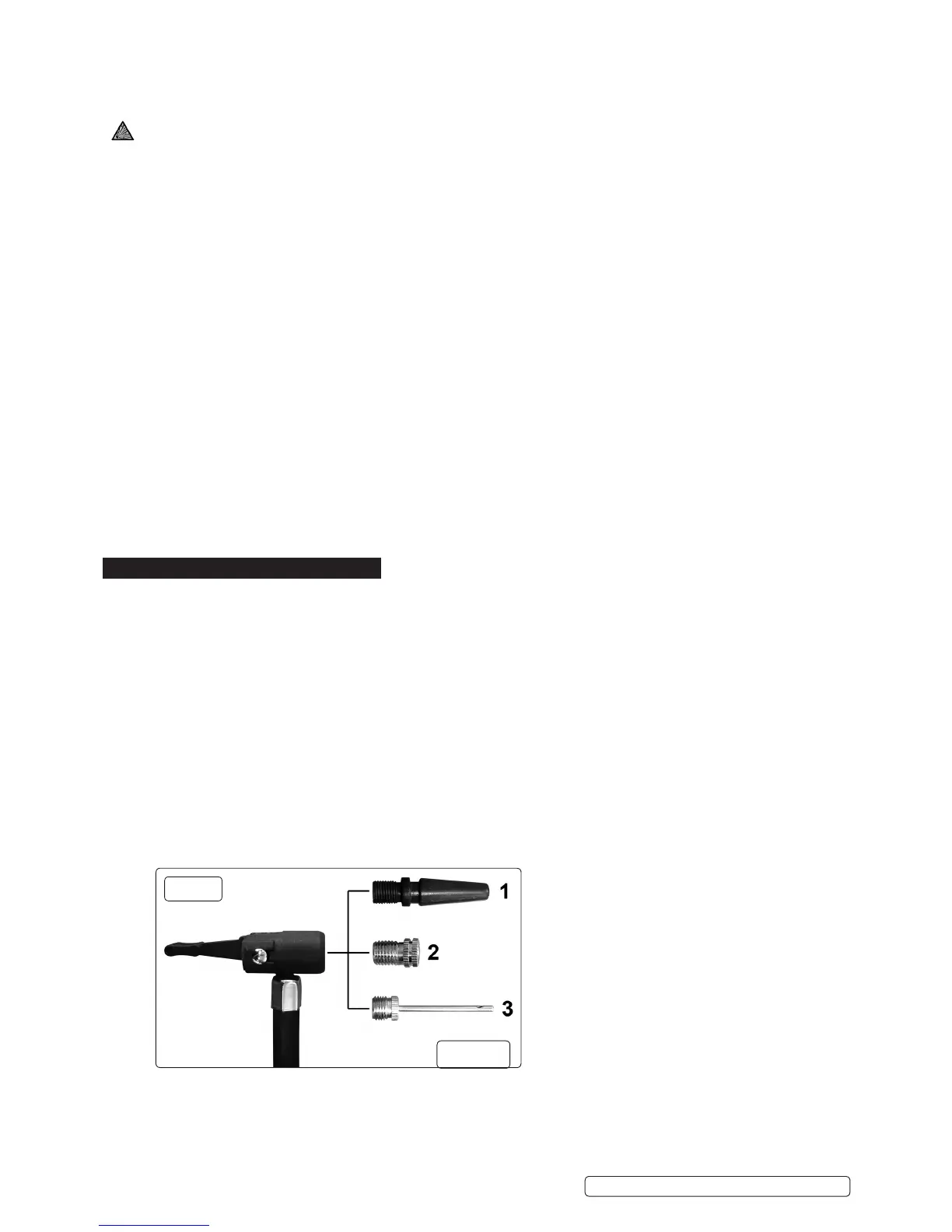
7.2.3. Identifythecorrectadaptorfortheproductandinsertitintotheinationconnectorasindicateding.9andpushthelocking
lever through 90º to lock it.
7.2.4. Insert the other end of the adaptor into the valve as far as possible.
7.2.5. Switch on the compressor using the switch on the unit (seeg.2-16)andmonitorthepressureontheairpressuregauge
(seeg.2-15).
7.2.6. When the desired pressure is reached, turn off the compressor, rotate the connector lever to the upright position and remove it
g.9
RS132
RS131.V3 RS132 | Issue 5(I) 04/01/16
Original Language Version
© Jack Sealey Limited
 Loading...