EasyManua.ls Logo

Sealey SA400 User Manual

Sealey SA400
2 pages
To Next Page IconTo Next Page
Page #1 background imageLoading...
Page #1 background image
DIGITAL TYRE INFLATOR WITH CLIP-ON
CONNECTOR
MODEL NO: SA400
Thank you for purchasing a Sealey product. Manufactured to a high standard, this product will, if used according to these instructions,
and properly maintained, give you years of trouble free performance.
IMPORTANT: PLEASE READ THESE INSTRUCTIONS CAREFULLY. NOTE THE SAFE OPERATIONAL REQUIREMENTS, WARNINGS & CAUTIONS. USE
THE PRODUCT CORRECTLY AND WITH CARE FOR THE PURPOSE FOR WHICH IT IS INTENDED. FAILURE TO DO SO MAY CAUSE DAMAGE AND/OR
PERSONAL INJURY AND WILL INVALIDATE THE WARRANTY. KEEP THESE INSTRUCTIONS SAFE FOR FUTURE USE.
1. SAFETY
9 Disconnect the gauge from the air supply before servicing or performing any maintenance.
9 Maintain the gauge in good condition (use an authorised service agent), and keep the gauge clean for best and safest performance.
9 Replace or repair damaged parts. Use recommended parts only. Unauthorised parts may be dangerous and will invalidate the warranty.
9 Locate gauge in a suitable work area, keep area clean and tidy and free from unrelated materials and ensure there is adequate lighting.
9 Keep children and unauthorised persons away from the work area.
8 DO NOT direct gauge outlet at yourself or at other persons or animals.
8 DO NOT carry by the hose, or yank the hose from the air supply.
8 DO NOT use the gauge for a task which it is not designed to perform.
8 DO NOT operate the gauge when you are tired or under the influence of alcohol, drugs or intoxicating medication.
8 DO NOT operate gauge if parts are missing or the gauge is damaged, as this may cause failure and/or personal injury.
2. INTRODUCTION
Die cast body and digital type gauge with rubber protector. Displayed in psi, bar, kpa and kg/cm². Fitted with 500mm rubber hose and
single clip-on connector.
3. SPECIFICATION
Model no ..................................................................... SA400
Max. air supply ............................................................ 250psi
Pressure units .................................. psi, bar, kpa and kg/cm²
Range ................................................................... (0-250psi)
Inlet size ....................................................................1/4”BSP
Battery .......................................................................2 x AAA
4. OPERATION
4.1. Theairsupplymustbecleananddry,useasuitablelter/watertrap.
4.2. Thesupplypressuremustbetospecication(seeabove).
4.3. Max. available pressure can not exceed the supply pressure.
4.4. TURN ON
4.4.1. Press On/Off button.
4.4.2. Press again to scroll through units.
4.4.3. Press light On/Off button to turn light off (if not required).
4.5.
ATTACH ADAPTOR TO VALVE
4.5.1. Push down clip and place the connector onto the tyre valve.
4.5.2. The connector will now be locked in place.
4.6. TO INFLATE
4.6.1. Momentarily depress the operation lever fully, then release to
display tyre pressure.
4.7. Fullydepressleverforanappropriateperiod.Avoidoverination,releaseleverfrequentlytocheckthepressure.
TO DEFLATE
4.7.1. Depressdeatebutton(untilaircanbeheardescaping)foranappropriateperiod.Fullydepresslevermomentarilythenreleaseto
display new pressure.
IMPORTANT - ALWAYS FULLY DEPRESS LEVER MOMENTARILY BEFORE READING TYRE PRESSURE.
Refer to
instruction
manual
Wear eye
protection
Original Language Version
© Jack Sealey Limited
SA400 | Issue:1 07/11/19
Question and Answer IconNeed help?

Do you have a question about the Sealey SA400 and is the answer not in the manual?

Sealey SA400 Specifications

General IconGeneral
BrandSealey
ModelSA400
CategoryPower Tool
LanguageEnglish

Summary

Safety

General Safety & Maintenance

Ensure proper maintenance, work area conditions, and personnel safety for optimal performance.

Prohibited Operations

Avoid misuse, operation under influence, or with damaged/missing parts for safety and warranty.

Introduction

Specification

Operation

Attach Adaptor to Valve

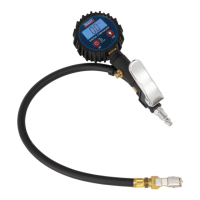
Connect the clip-on connector securely to the tyre valve for operation.

Turn On and Unit Selection

Power on the device and scroll through available pressure units (psi, bar, kpa, kg/cm²).

Inflate Tyre Pressure

Use the lever to inflate tyre pressure, checking frequently to avoid over-inflation.

Deflate Tyre Pressure

Press the deflate button to release air and adjust pressure to the desired level.

Maintenance

Periodic Checks and Maintenance

Perform weekly operation checks and quarterly calibration for sustained accuracy.

Battery Change

Replace batteries when the display fails to illuminate, observing polarity.

Environmental and Disposal Information

WEEE Regulations

Dispose of product responsibly according to EU directive for waste electrical and electronic equipment.

Battery Removal and Disposal

Information on battery regulations and safe disposal of batteries.

Environmental Protection

Recycle unwanted materials and dispose of product and fluids according to local regulations.

Related product manuals