EasyManua.ls Logo

Sears 103.23620 - Assembling Your Drill Press; Drill Press Installation

Sears 103.23620
6 pages
Print Icon
To Next Page IconTo Next Page
To Previous Page IconTo Previous Page
Loading...
OPERATING INSTRUCTIONS
AND
PRICE
LIST
FOR DRILL
PRESS
Model
Number
103.23620
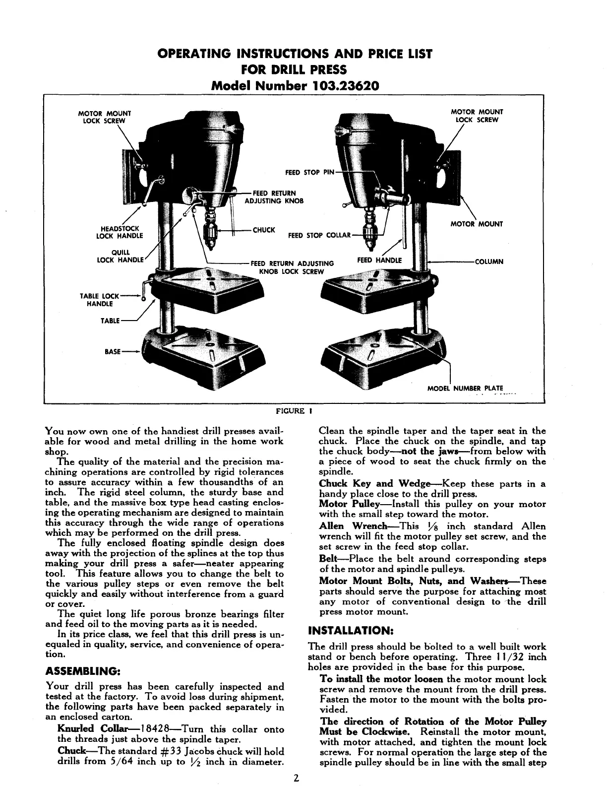
TABLE
LOC:K
--.11
HANDLE
FIGURE I
You
now
own
one
of
the
handiest
drill
presses
avail·
able
for
wood
and
metal
drilling
in
the
home
work
shop.
The
quality
of
the
material
and
the
precision
ma·
chining
operations
are
controlled
by
rigid
tolerances
to
assure
accuracy
within
a
few
thousandths
of
an
inch.
The
rigid
steel
column,
the
sturdy
base
and
table,
and
the
massive
box
type
head
casting
enclos·
ing
the
operating
mechanism
are
designed
to
maintain
this
accuracy
through
the
wide
range
of
operations
which
may
be
performed
on
the
drill
press.
The
fully
enclosed
floating
spindle
design
does
away
with
the
projection
of
the
splines
at
the
top
thus
making
your
drill
press
a
safer-neater
appearing
tool.
This
feature
allows
you
to
change
the
belt
to
the
various
pulley
steps
or
even
remove
the
belt
quickly
and
easily
without
interference
from
a
guard
or
cover.
The
quiet
long
life
porous
bronze
bearings
filter
and
feed
oil
to
the
moving
parts
as
it
is
needed.
In
its
price
class,
we
feel
that
this
drill
press
is
un·
equaled
in
quality,
service,
and
convenience
of
opera·
tion.
ASSEMBLING:
Your
drill
press
has
been
carefully
inspected
and
tested
at
the
factory.
To
avoid
loss
during
shipment,
the
following
parts
have
been
packed
separately
in
an
enclosed
carton.
Knurled
Collar-18428-Turn
this
collar
onto
the
threads
just
above
the
spindle
taper.
Chuck-The
standard
#33
Jacobs
chuck
will
hold
drills
from
5/64
inch
up
to
Y2
inch
in
diameter.
2
Clean
the
spindle
taper
and
the
taper
seat
in
the
chuck.
Place
the
chuck
on
the
spindle,
and
tap
the
chuck
body-not
the
jawa--from
below
with
a
piece
of
wood
to
seat
the
chuck
firmly
on
the
spindle.
Chuck
Key
and
Wedge--Keep
these
parts
in
a
handy
place
close
to
the
drill
press.
Motor
PuDey-Install
this
pulley
on
your
motor
with
the
small
step
toward
the
motor.
ADen
Wrench-This
Va
inch
standard
Allen
wrench
will fit
the
motor
pulley
set
screw,
and
the
set
screw
in
the
feed
stop
collar.
Belt-Place
the
belt
around
corresponding
steps
of
the
motor
and
spindle
pulleys.
Motor
Mount
Bolts,
Nuts,
and
Washers--
These
parts
should
serve
the
purpose
for
attaching
most
any
motor
of
conventional
design
to
the
drill
press
motor
mount.
INSTALLATION:
The
drill
press
should
be
holted
to
a
well
built
work
stand
or
bench
before
operating.
Three
11/32
inch
holes
are
provided
in
the
base
for
this
purpose.
To
install
the
motor
loosen
the
motor
mount
lock
screw
and
remove
the
mount
from
the
drill
press.
Fasten
the
motor
to
the
mount
with
the
bolts
pro·
vided.
The
direction
of
Rotation
of
the
Motor
PuUey
Must
be
Clockwise.
Reinstall
the
motor
mount,
with
motor
attached,
and
tighten
the
mount
lock
screws.
For
normal
operation
the
large
step
of
the
spindle
pulley
should
be
in
line
with
the
small
step
..
'-,