2
Hynautic Hydraulic Engine Controls – 04 Series
5Ê /iÊÃi`iÀ½ÃÊ«ÀÌÃÊ>ÀiÊÌ>««i`Ê£É{¸Ê */°Ê-ÕÌ>LiÊ>`>«ÌiÀÃÊ
ÕÃÌÊLiÊÃÌ>i`ÊÌÊ>VVi«ÌÊÌiÊÌÕL}ÊÕÃi`°ÊÌÊÃÊÀiÊVÛiiÌÊ
ÌÊÃÌ>ÊÌiÃiÊ>`>«ÌiÀÃÊ«ÀÀÊÌÊÕÌ}ÊÌiÊÃi`iÀðÊ
ÃÌÀÕVÌÃÊvÀÊV««iÀÊÌÕL}ÊÃÌ>>ÌÃÊ>ÀiÊ«>}iÊ£Ó°®
6Ê -iVÕÀiÊÃi`iÀÃÊ«iÀÊ}ÕÀiÊÓÊvÀÊÃ}iÊi>`]ÊÀÊ}ÕÀiÊÎÊvÀÊÃ`iÊ
LÞÊÃ`iÊÕÌ}°
7Ê
/iÊÃi`iÀ½ÃÊ>`iÊ«ÃÌÊ>ÞÊLiÊÃiÌÊÜÌÊÌÃÊLÞÊÃi}
Ê
ÌiÊÌ}Ìi}ÊÃVÀiÜÊÕÃ}Ê>Ê£É{¸Ê>iÊÜÀiV®ÊÊÌiÊÜiÀÊi`Ê
vÊÌiÊ>ÀÊ>`ÊÌiÊÀÌ>Ì}ÊÌiÊ>ÀÊ>ÃÊ`iÃÀi`Ê>`ÊÀiÃiÌÌ}ÊÌiÊ
ÃVÀiÜ°ÊvÌiÀÊÌiÊ>ÀÊÃÊÃiÌ]ÊÌÊÜÊ>ÛiÊ>Ê££xcÊ>ÝÕÊ>ÀV°
8Ê -iVÕÀiÊÌiÊÀi>}ÊÃi`iÀÃÊ«iÀÊ-Ìi«ÃÊ£ÊÌÀÕ}ÊÇ°
If the area under the control
panel is too confined to allow
the tubing to be connected with
moderate ease, do not secure
the sender at this time. Proceed
with the installation of the
remaining senders per Steps 1
through 5. The sender may be
secured after the tubing has
been connected to it.
NOTICE
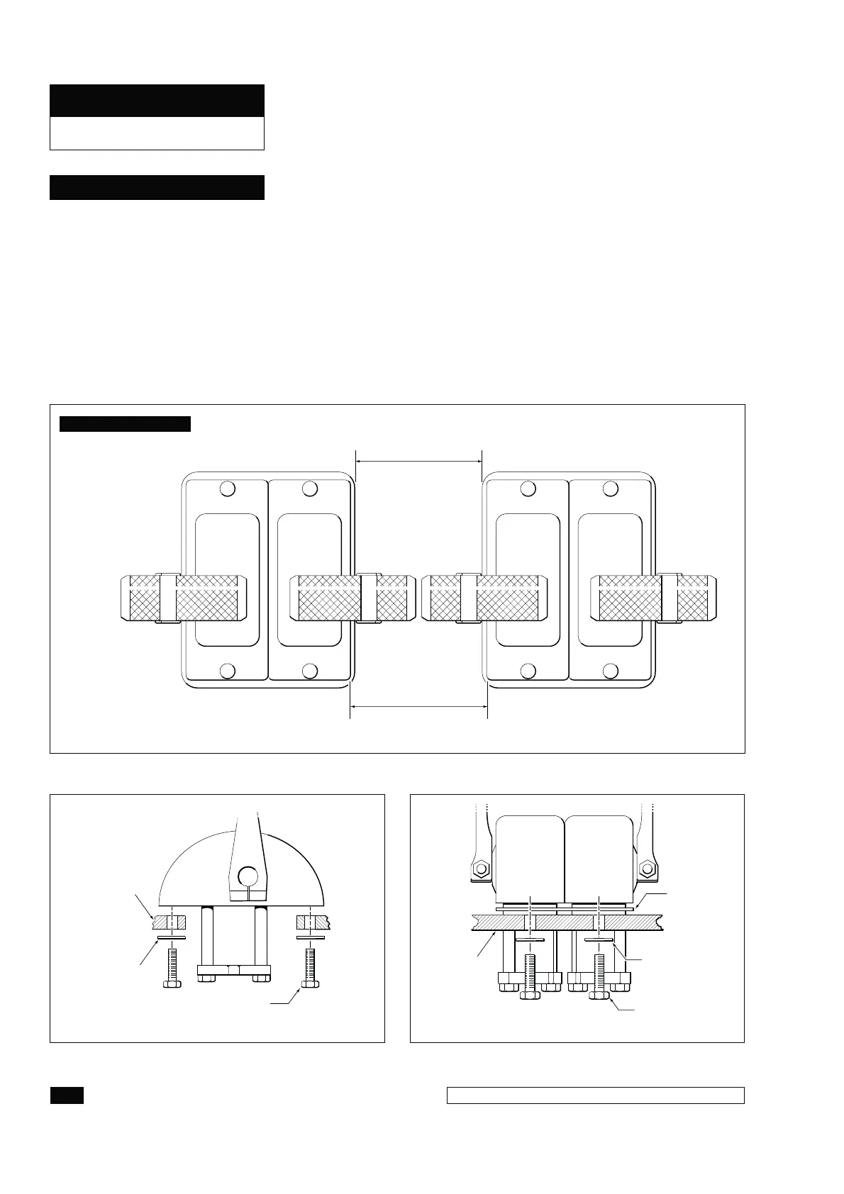
3.75" MINIMUM
BETWEEN HEADS
3.5" MINIMUM
BETWEEN PLATES
Figure 1. Mounting "T" Handle Controls Side by Side.
CONTROL
PANEL
CDF-04
MOUNTING
PLATE
WASHER
MOUNTING
BOLT
Figure 3. Side-By-Side Senders.
WASHER
PANEL
MOUNTING
BOLT
Figure 2. Single Head Sender.
The minimum distance
does not apply to
installations using
the "knob style"
control handles.
NOTICE
COMPONENT INSTALLATION
HYNAUTIC CONTROLS
 Loading...