Installation Instructions & Owner's Manual
3
-i>-Ì>ÀÊ-ÕÌÃÊÌÀÌÌiÊÃ>ÛiÃÊÕÃÌÊLiÊÕÌi`ÊÃÊÌ>ÌÊ>ÌÊÌiÊ
`ÃÌÀiÊvÊLÌÊÌiÊi}i½ÃÊÌÀÌÌiÊ>ÀÊ>`ÊÌiÊÃ>Ûi½ÃÊVÌÀÊ
>À]ÊÌiÞÊ>Ài\Ê£®ÊÊÌiÊÃ>iÊ«>iÆÊӮʫ>À>iÊÌÊi>VÊÌiÀÆÊ>`ÊήÊ
À}ÌÊ>}iÃÊÜÊLiÊvÀi`ÊLiÌÜiiÊÌiÊViVÌ}Ê>}iÊ>`Êi>VÊ
>À°Ê-iiÊ}ÕÀiÊ{°
vÊÌiÃiÊVÀÌiÀ>Ê>ÀiÊiÌ]Ê>Ê`i>ÊÃÌ>>ÌÊÜÊÀiÃÕÌ°
ÊëÀ}ÊLÕ}iiL>ÊÌÊ>ÃÃiLÞÊÃÊvÕÀÃi`ÊÜÌÊi>VÊÌÀÌÌiÊ
Ã>Ûi°ÊÌÊÃÊÃÌ>i`ÊÊÌiÊÃ>ÛiÊ>ÀÌÊÌÀÌÌiÊ>}iÊ>VVÀ`}ÊÌÊ
}ÕÀiÊ{°ÊÌÊ>ÜÃÊÕ«ÊÌÊÎɣȸÊÃ>ÛiÊ>ÀÊÛiÀÌÀ>ÛiÊÊi>VÊ`ÀiVÌ°Ê
/ÃÊÛiÀÌÀ>ÛiÊiÌÃÊÌiÊÃ>ÛiÊVÞ`iÀÊÌÀ>ÛiÊÌÃÊvÕÊÃÌÀiÊ>`ÊÃÌÊ
«ÀÛ`iÊvÕÊÌÀ>ÛiÊÌÊÌiÊÌÀÌÌiÊ>À°Ê9ÕÊÕÃÌÊÕÃiÊ>ÃÌÊ>ÊvÊÌiÊ
Ã>ÛiÊÌÀ>Ûi]ÊÀÊ>LÕÌÊÇxc]ÊÌÊ«iÀ>ÌiÊÌiÊÌÀÌÌi°Ê/iÊÃ>ÛiÊÕÃÌÊ}Ê
vÕÊÃÌÀiÊÊi>VÊ`ÀiVÌÊÊÀ`iÀÊÌÊÃÞVÀâiÊÌiÊÃÞÃÌi°
/iÊÌÀÌÌiÊÃ>Ûi½ÃÊ>ÀÊ>ÞÊLiÊÃiÌÊÌÊ>ÞÊ`iÃÀi`Ê«ÃÌÊLÞÊÃi}
Ê
ÌiÊÌ}Ìi}ÊÃVÀiÜÊÕÃ}Ê>ÊÎɣȸÊ>iÊÜÀiV®ÊÊÌiÊÜiÀÊi`ÊvÊ
ÌiÊ>ÀÊ>`ÊÌiÊÀÌ>Ì}ÊÌiÊ>ÀÊ>ÃÊ`iÃÀi`Ê>`ÊÀiÃiÌÌ}ÊÌiÊÃVÀiÜ°Ê
vÌiÀÊÌiÊ>ÀÊÃÊÃiÌ]ÊÌÊÜÊ>ÛiÊ>ÊÇncÊ>ÝÕÊ>ÀV°
Throttle Slave Installation
The standard SeaStar Solutions
System,
MC-04, uses the ST-06
Integrated Throttle Slave. You may
have chosen to order a non-
standard system which includes
the ST-04 Throttle Slave and
STV-10 Lock-out Valve. Depending
on which system you have, follow
the corresponding installation
instructions in this section.
NOTICE
The Throttle Slave must not be mounted to any surface exceeding
220° F (103° C). If mounting in a "hot spot" is unavoidable, the
slave must be insulated from the heat.
CAUTION
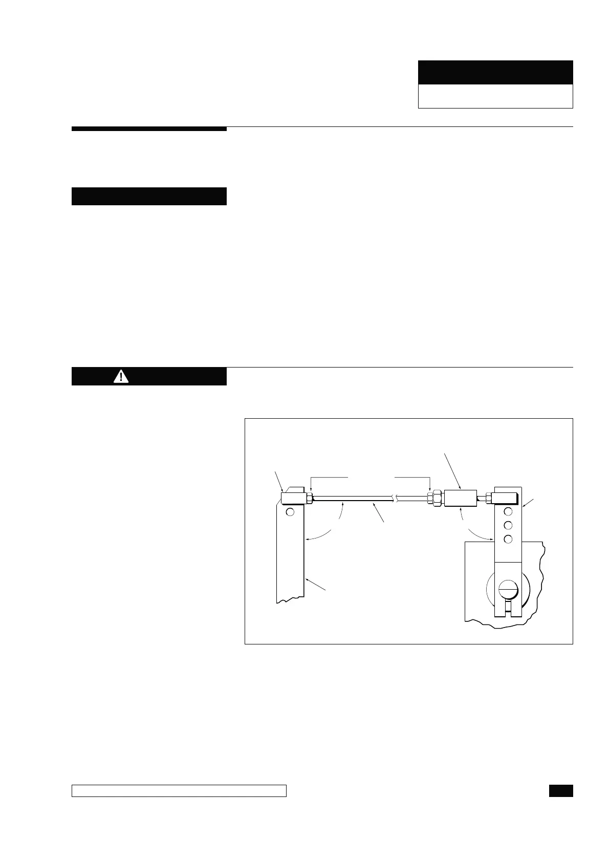
BALL JOINT
(670010)
LOCK NUTS
(1/4-20)
BUNGEE-BALL
JOINT ASSEMBLY
(850081)
SLAVE
ARM
THROTTLE ARM
1/4-20
THREADED
ROD
90˚
90˚
Figure 4. Throttle Slave to Throttle Arm Installation.
Steps 1 through 8 apply to both ST-04 and ST-06 Systems
1Ê -iVÕÀiÊÌiÊÕÌ}ÊLÀ>ViÌÊÌÊÌiÊi}i°ÊÊÃÕÌ>LiÊLÀ>ViÌÊ
ÕÃÌÊLiÊv>LÀV>Ìi`°
2Ê -iVÕÀiÊÌiÊÌÀÌÌiÊÃ>ÛiÊÌÊÌiÊÕÌ}ÊLÀ>ViÌÊÕÃ}ÊÎÉn£ÈÊ
ÕÌ}ÊLÌð
3Ê ÃÌ>Ê>ÊVÊÕÌÊ>`ÊLÕ}iiL>ÊÌÊÊÌiÊi`ÊvÊ>Ê£É{ÓäÊ
ÃÌ>iÃÃÊÀÊLÀ>ÃÃÊÌÀi>`i`ÊÀ`°
COMPONENT INSTALLATION
HYNAUTIC CONTROLS
 Loading...