10
– Mark drill holes for the heel plate.
– Drill using a 5 mm drill bit.
– Push the rawlplugs supplied into the
holes.
– Mount the heel plate and the spacers
using two screws.
– Remove the cable tie (provided for
transport purposes) on the top measur-
ing rod.
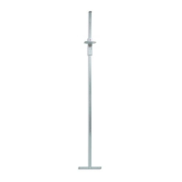
– Push the top measuring rod onto the
plastic guide of the bottom measuring
rod and screw it tight using the pan-
head tapping screw.
– Place the bottom measuring rod on the
heel plate and hold the measuring rod
up to the desired point of attachment.
Use a spirit level to align it in the perpen-
dicular.
– Mark the drill hole for the measuring
rod.
– Drill using a 5 mm drill bit.
– Push the rawlplug into the hole.
– Push the bottom measuring rod onto
the heel plate.
– Put the spacers between the measuring
rod and the wall and fix the measuring
rod in position.
1.
2.
3.


 To Next Page