Seca 717/727/728/737/748/757 Description of faults
23.04.97 - Jen Blatt 4 30-34-00-437 Index G
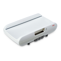
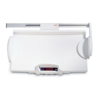
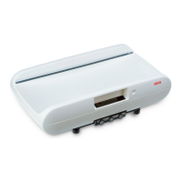
Model 748
Check the cables between the main board and
the supplementary board:
- Check the soldered connections
- Measure the signals 5V, GND, REF, TEST on
the
supplementary board
- Measure the COM signal on the main board
- If a signal is not transmitted, replace the cable
Please refer to the oscillograms below when
checking the signals. The pulse widths of the
REF and COM signals vary with the load.
Check the force sensor connection:
Check the soldered connections (for seca 748
see drawing 08-06-04-541).
If all cables are okay, there is a fault on the AD
converter or the microprocessor is not working
properly.
If the supplementary AD converter board on
model 748 is replaced, the scale must be
calibrated according to calibration instructions
30-34-00-446 and adjustment instructions 30-
34-00-487.
Important note: Apply Sylgard 170 A&B to
seal the supplementary board
The scale must be recalibrated.
 Loading...