571 Operation/Maintenance Instructions Page 9 of 19
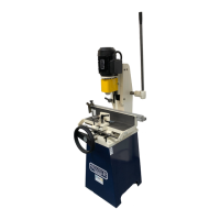
3.0 Installation
1. Remove the protective rust preventative using turpentine or paraffin. Do not use any solvent,
petrol or gas oil, which might dull or oxidise the paintwork. Lightly oil cleaned surfaces to
prevent rusting.
2. The counterbalance weight is fastened to the inside of the machine stand for transport
purposes and should be released prior to operation. Remove the bolt at the rear of the stand
whilst at the same time exerting downward pressure on the operating lever, this will enable
the weight to drop safely into its operating position.
3. Take the oil nipples from the toolkit and insert them into the two M8 tapped holes at the
centre of the rear of the column.
4.0 Electrical Installation
Electrical wiring should be carried out by a competent electrician following the directions given
below. Reference should be made to the appropriate wiring installation rules, e.g. in the UK the
16
th
edition of the IEE Wiring Regulations for Electrical Installation (BS7671).
The motor and starter have been wired in at the factory and tested before despatch.
All that is required is to connect the power supply to the starter from your isolator.
Check that the supply details on the motor plate correspond with the site supply.
It is important that the correct cable size is used to avoid a voltage drop at the motor
terminals. If the motor is operated on a voltage outside, plus or minus 6% of the spot
voltage, then premature failure will occur.
It is important to check rotation of the motor which should be clockwise when viewed
from above the machine.
Should you encounter problems on start up check for the following likely causes:
Main supply switched off
Overload tripped
Fuse blown
Loose wire
Coil failure
Check main switch
Reset overload
Check and replace fuses (check all
three on three phase)
Check all connections
Check circuit of hold in coil
Overload trips during
starting
Low voltage
Low voltage
Low voltage
Check supply-voltage both on no load
and on moment of switch on. Allowed
variation plus/minus 6%
Check that correct cable size has been
used to install the machine. Change if
necessary.
Long runs of cable can cause voltage
drop. Check that voltage is not outside
the minus 6% tolerance.
Re-site the machine nearer supply or
increase the cable size to compensate.
 Loading...