Cal. 5M84A
14/21
TECHNICAL GUIDE
l
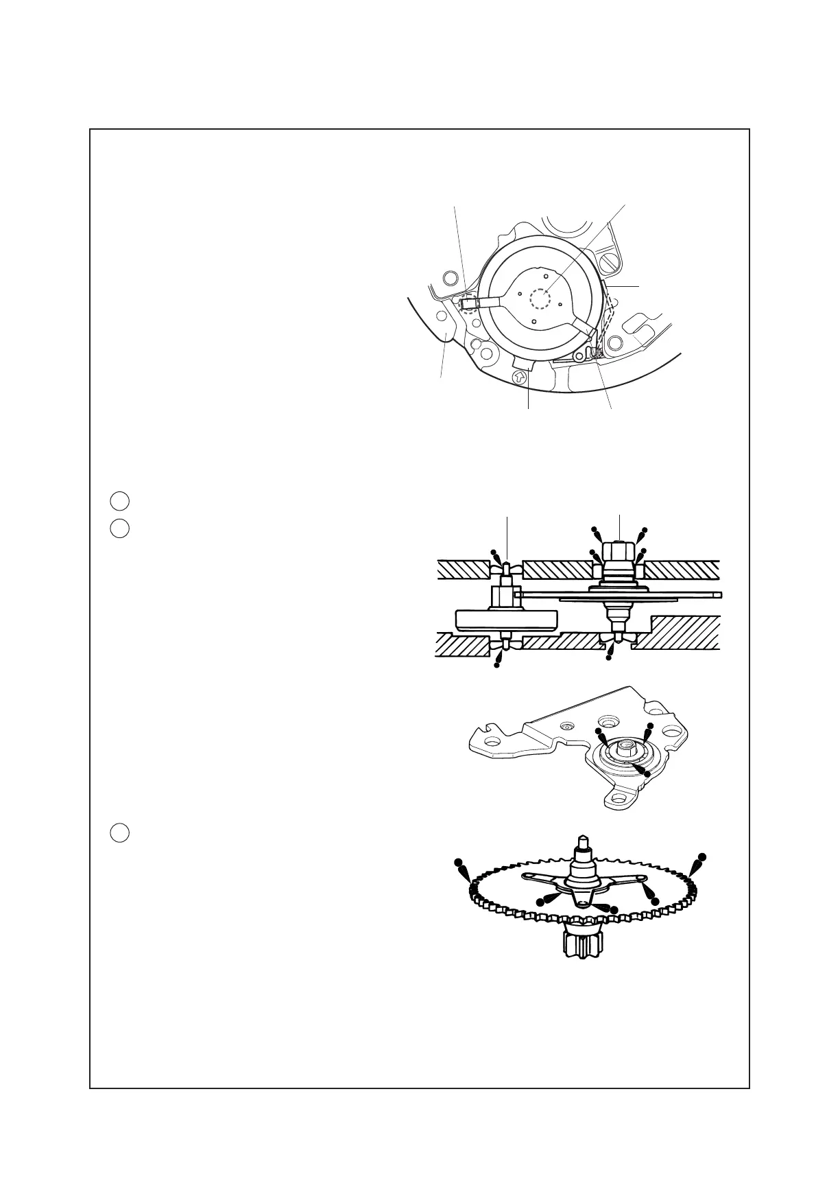
Automatic generating mechanism
• Howtoremove
Insert the tip of tweezers into the “C”
portiongapintheillustrationatright,and
pry up the RECHARGEABLE BATTERY
UNIT to remove it.
• Howtoinstall
Set the “A” portion of the minus lead
terminal to the hole of the MAINPLATE,
andpushthe“B”portiondownvertically
so that the RECHARGEABLE BATTERY
UNIT is well seated in position.
Note: Take utmost care not to short-circuit
the (+) and (-) terminals, as this will
deteriorate the battery unit.
“A” portion
Main plate
メCメ portion Minus lead terminal
Rechargeable
battery plus
terminal
メBメ portion
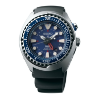
39 OSCILLATINGWEIGHTBRIDGESCREW
41 OSCILLATINGWEIGHTBRIDGE
Before tightening the OSCILLATING WEIGHT
bridgescrew,checkthattheupperpivotofthe
GENERATINGROTOR is inserted properly into
the pivot jewel.
Be sure to lubricate the upper and lower pivots
of GENERATING ROTOR and INTERMEDIATE
WHEEL FOR GENERATING ROTOR with the
proper oil in the quantity specied in the
illustration.
Lubricate the ball-bearing of the OSCILLATING
WEIGHT BRIDGE as shown in the illustration
at right.
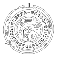
Intermediate wheel for
generating rotor
Generating rotor
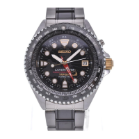
43 INTERMEDIATEWHEELFORGENERATINGROTOR
• Lubricating
Refer to the illustration at right.
Note: B e s u r e t o o b s e r v e t h e p o s i t i o n , t y p e o f o i l
andquantityofthelubricationspecied
in the illustration.
• Lubricating