No. 2
No. PROCESS ILLUSTRATION AND SPECIAL INSTRUCTIONS
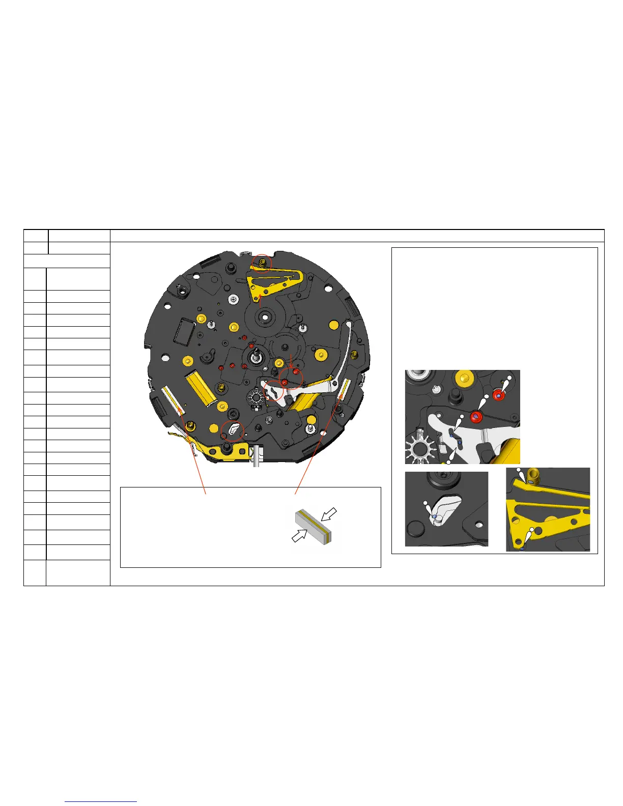
Lubrication
Lubricate 1 to 5
as illustrated.
47
Assemble the
CONNECTOR A.
46
Assemble the
CONNECTOR B.
Lubricate 1 to 5 as illustrated.
Lower pivots of the GENERATING ROTOR and the
intermediate wheel (see Fig. 2-1).
A guiding slit of the PIEZOELECTRIC MOTOR SETTING
LEVER (See Fig. 2-1.).
A guiding slit of the SETTING LEVER (see Fig. 2-2).
Contact point of the CONTROL JUMPER and the post with a
screw hole for the CALENDAR TRAIN BRIDGE SCREW (See
Fig. 2-3).
Contact point of the CONTROL JUMPER and the CALENDAR
CONTROL WHEEL (See Fig. 2-3).
Lower pivots of the
GENERATING
ROTOR and the
Intermediate wheel
<47> Set the CONNECTOR A. <46> Set the CONNECTOR B.
Gently hold the lateral sides of the connector
so as not to bed or deform the gold layer inside
(Fig. 2-4).
Fig.2-2
Fig.2-3
Fig.2-4
Fig.2-1
Type of oil: AO-3