Technical Guide
No. 6
No. PROCESS ILLUSTRATION AND SPECIAL INSTRUCTIONS
33
Assemble the
PIEZOELECTRIC
STATOR BLOCK.
32
Assemble the
PIEZOELECTRIC
MOTOR
CONDUCTIVE
PLATE.
31
Assemble the
PIEZOELECTRIC
MOTOR.
30
Assemble the
PIEZOELECTRIC
ROTOR BLOCK.
29
Assemble the 1
ST
Piezoelectric rotor.
28
Set the
PIEZOELECTRIC
MOTOR SPRING
rotor block.
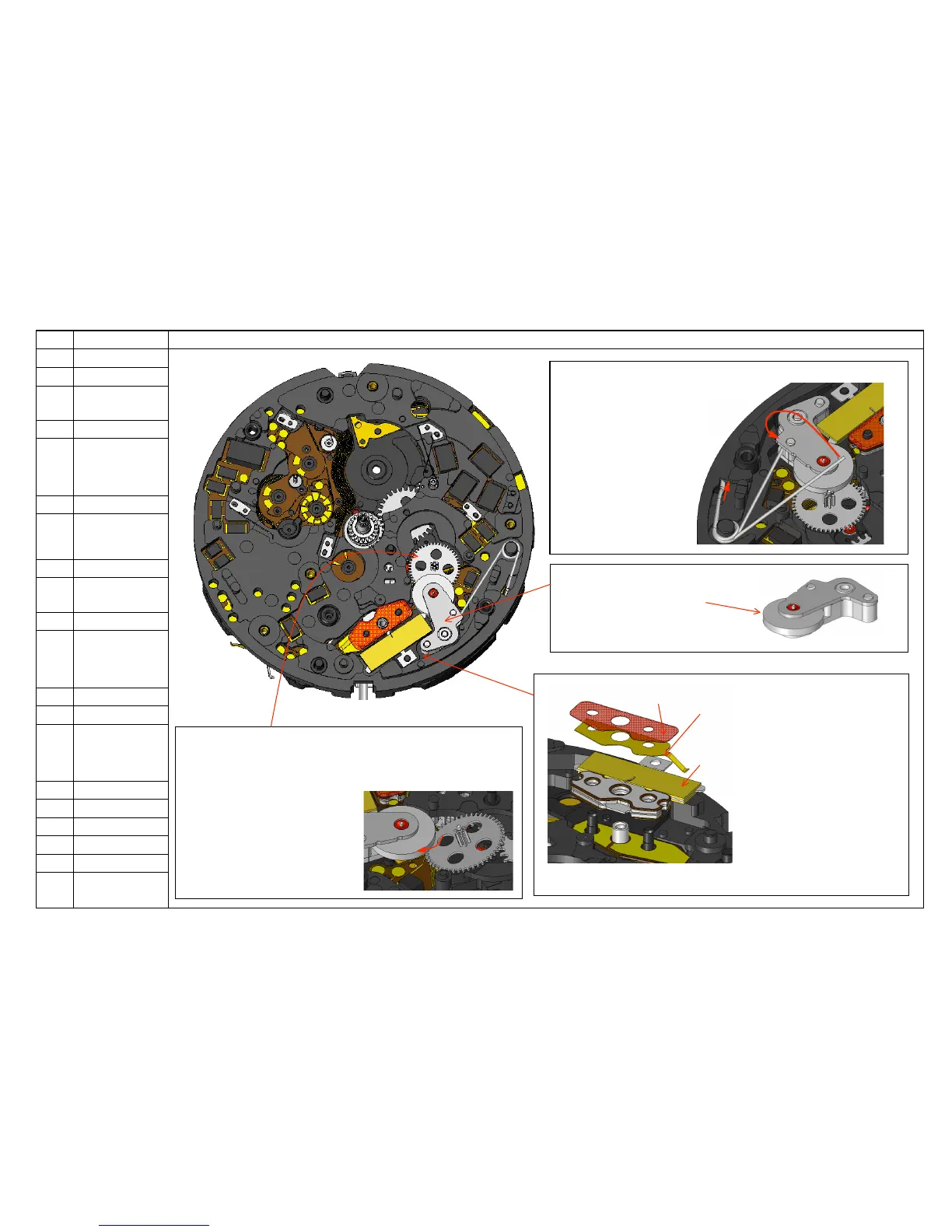
3133
Mount the stator block, the conductive
plate and the insulator (Fig.6-1).
When assembling the stator block,
do not touch the stator itself, but
hold the conductive part so as not
to distort or deform it.
30Assemble the PIEZOELECTRIC ROTOR BLOCK
Make sure that there are no scratches,
dirt, dusts or stains on the
surface of the rotor (see Fig.6-2).
28Set the PIEZOELECTRIC MOTOR SPRING and secure it to the rotor block
1. While inserting the tip of the spring
Into the hole of the plate, set it to
The support pin of the plate.
2. Secure the spring to the rotor
underneath the bridge part
of the rotor block.
29 Assemble the 1
ST
INTERMEDIATE DATE WHEEL underneath the
Piezoelectric rotor.
Make sure that the pinion of the
Rotor and the teeth of the wheel
are properly meshed (Fig 6-3).
Fig. 6-3
Fig. 6-2
Fig. 6-1
Fig. 6-4
33