TECHNICAL GUIDE
Cal. V115A
10/16
l
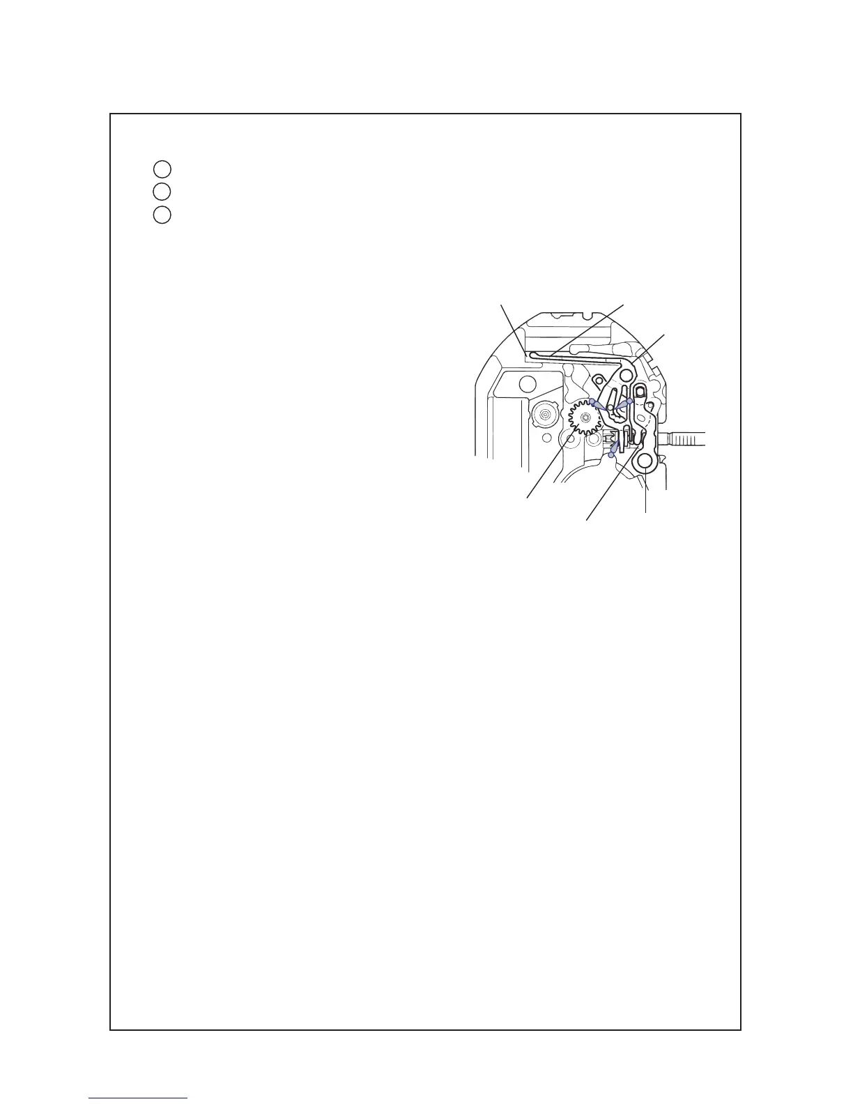
Setting mechanism - Assembly position and lubrication instructions
• Setting position and lubricating
Refer to the illustration below for the setting position and lubrication of the respective parts.
catch the protruded portion of the main plate
("A" portion in the illustration).
Note: Take care not to install the setting lever
spring upside down. (Refer to the
illustration at right.)
“A” portion
Setting lever spring
Spring portion of the yoke
Setting lever
Minute wheel
Yoke
wd
w;
ws