4
TDST24M000SE 032635 190619
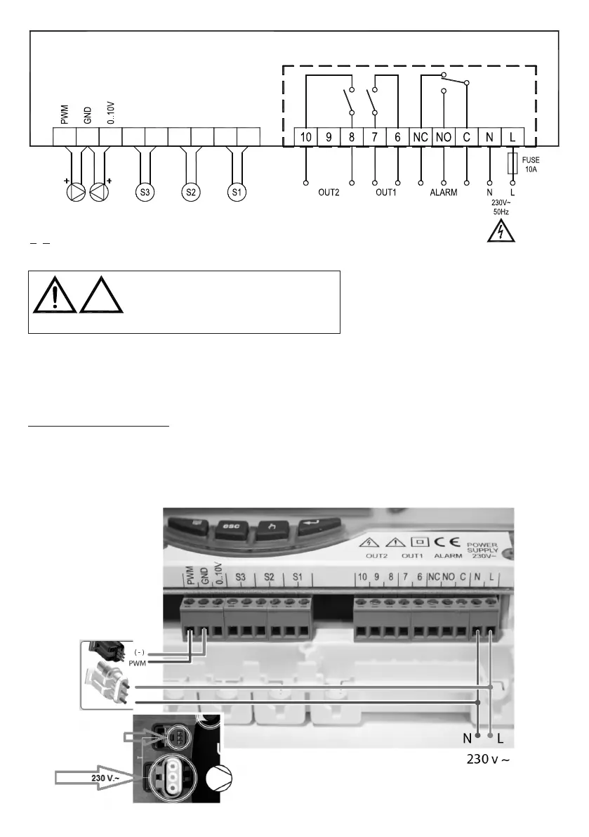
WIRING EXAMPLE ONLY FOR SOLAR CIRCULATORS IN ACCORDANCE WITH DIRECTIVE ErP 2015 WITH
EXTERNAL PWM SIGNAL.
PWM signal
WARNING!
?
Before wiring the appliance be sure to turn the mains power off.
WARNING! S1, S2 and S3 are NTC temperature sensors. For S1 sensor the -50°C..+200°C range probe (blue cable) must be
used, while the probes with the range of -50°C..+110°C (yellow cable) can be used for the other probes.
The outputs OUT1, OUT2 and Alarm, are voltage free. It is advisable to t a 10A 250V~ fuse on the power unit mains capable
to intervene in case of short circuits on loads.
TERMINAL BOARD GROUNDING: On the base of the control unit case is located a brass terminal board for connecting the
ground protection conductors of the load devices connected to the control unit.
: reinforced insulation