Do you have a question about the Sel SEL-351A and is the answer not in the manual?
| Frequency | 50/60 Hz |
|---|---|
| Communication Protocols | DNP3, Modbus, IEC 61850 |
| Mounting | Panel Mount |
| Display | LCD |
| Current Rating | 5 A |
| Protection Functions | Overcurrent |
| Inputs | Analog, Digital |
| Outputs | Relay |
| Operating Temperature | -40°C to 70°C |
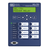
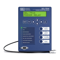
Details about the different SEL-351A relay models, including their rack unit height, I/O contacts, and display options.
Overview of the manual's sections, detailing the content of each section from Installation to Command Summary.
Provides dimensional details for rack-mount and panel-mount models, including panel cutout dimensions.
Illustrates the rear-panel connection layout for horizontal models, showing terminal assignments.
Details on connecting screw-terminal blocks, power supply, optoisolated inputs, and current transformer inputs.
Step-by-step instructions for accessing the relay's circuit boards, including removing cables and the drawout tray.
Explains the correspondence between output contact jumpers and output contacts, including 'a' and 'b' type contacts.
Details on instantaneous and definite-time overcurrent elements, including settings, accuracy, and pickup operation.
Explains phase, neutral ground, residual ground, and negative-sequence time-overcurrent elements, including curves and settings.
Describes voltage elements, values, and settings for undervoltage and overvoltage protection.
Details on synchronism check elements, including voltage inputs, settings, and operation.
Explains frequency elements, settings, and operation for over/underfrequency detection.
Explains the loss-of-potential logic and its settings (ELOP), including its impact on other elements.
Details the load-encroachment logic, its settings, and application for phase overcurrent elements.
Covers settings for directional control of overcurrent elements, including automatic and manual configurations.
Explains the flexible tripping logic, including DTT, TR5OTF, TR, ULTR, and TDURD settings.
Defines the labels and functions of the front-panel target LEDs for trip indication.
Details the logic controlling the close output contact for automatic reclosing and manual closing.
Explains the logic that supervises automatic reclosing, detecting open interval time-outs.
Describes the general states of the reclosing relay and their correspondence to relay word bits and front-panel LEDs.
Explains the operation of optoisolated inputs IN101 through IN106, including debounce timers.
Details the function and configuration of local control switches on models with an LCD.
Explains the concept of multiple setting groups and how to select the active group.
Describes SELOGIC control equation variables and timers (SV1-SV16) used for custom logic.
Explains the breaker monitor function for scheduling circuit breaker maintenance based on operations and current.
Describes the station DC battery monitor, including under/overvoltage detection and alarming.
Provides time-overcurrent curves and time dial settings for various inverse curve types.
Lists and defines relay word bits used in SELOGIC control equations and their primary applications.
Details serial port pinout definitions and provides cable diagrams for various connections.
Explains access levels 0, 1, B, and 2, detailing command availability and password requirements.
A comprehensive list of serial port commands, their descriptions, and corresponding front-panel pushbuttons.
Overview of front-panel pushbutton functions, including primary and secondary operations.
Explains how to configure and use the rotating default display feature on LCD models.
Details standard 15/30-cycle event reports, including report length and triggering conditions.
Provides guidance on retrieving full-length standard event reports with various formatting options.
Guidelines for performing acceptance testing to verify relay model compliance with specifications.
Steps for commissioning testing of a new protection system, including checking connections and auxiliary equipment.
Procedures for performing routine maintenance tests to ensure accurate measurement and proper function.
Provides procedures for diagnosing and resolving common relay issues like dark LEDs or lack of response.
Lists firmware part/revision numbers and descriptions of firmware differences across revisions.
Step-by-step instructions for upgrading the relay's firmware via a serial port.
Lists binary and ASCII configuration messages for controlling the relay.
Defines various message blocks like A5C0 Relay Definition Block and A5C1 Fast Meter Configuration Block.
Provides guidelines and examples for coordinating negative-sequence overcurrent elements with other protection elements.
Explains relay word bits and their operation using phase time-overcurrent element 51PT as an example.
Details SELOGIC control equation operators and provides examples for NOT, rising edge, and falling edge operators.
Explains how to configure the relay for DNP protocol, including port settings and parameters.
Describes methods for retrieving data via DNP, including polled static and unsolicited reports.
Provides a table of supported DNP objects, their descriptions, and request/response codes.
Compares settings and protective functions between SEL-351A, SEL-251, and SEL-267 relays.
Highlights key protective function differences, such as overcurrent, voltage, and directional elements.
Provides instructions for installing the SEL-5030 ACSELERATOR software on a PC.
Lists commands available at Access Level 1 for viewing settings and retrieving data.
Details commands for unlimited access to relay settings, parameters, and output contacts.
Explains key stroke commands for navigating menus and executing SET commands.