Schweitzer Engineering Laboratories, Inc. SEL-411L Data Sheet
23
Substation Battery Monitor for DC
Quality Assurance
The relay measures and reports the substation battery
voltage for up to two battery systems. The SEL-411L,
SEL-421, SEL-451 support two battery monitors while
the SEL-487B, SEL-487E, and SEL-487V support one.
Each battery monitor supports programmable threshold
comparators and associated logic provides alarm and
control for batteries and chargers. The relay also provides
dual ground detection. Monitor dc system status alarms
with an SEL communications processor and trigger mes-
sages, telephone calls, or other actions.
The measured dc voltage is reported in the
METER display
via serial port communications, on the LCD, and in the
event report. Use the event report data to see an oscillo-
graphic display of the battery voltage. Monitor the sub-
station battery voltage drops during trip, close, and other
control operations.
Breaker Contact Wear Monitoring
Circuit breakers experience mechanical and electrical wear
during each operation. Effective scheduling of breaker
maintenance takes into account the manufacturer’s pub-
lished data of contact wear versus interruption levels and
operation count.
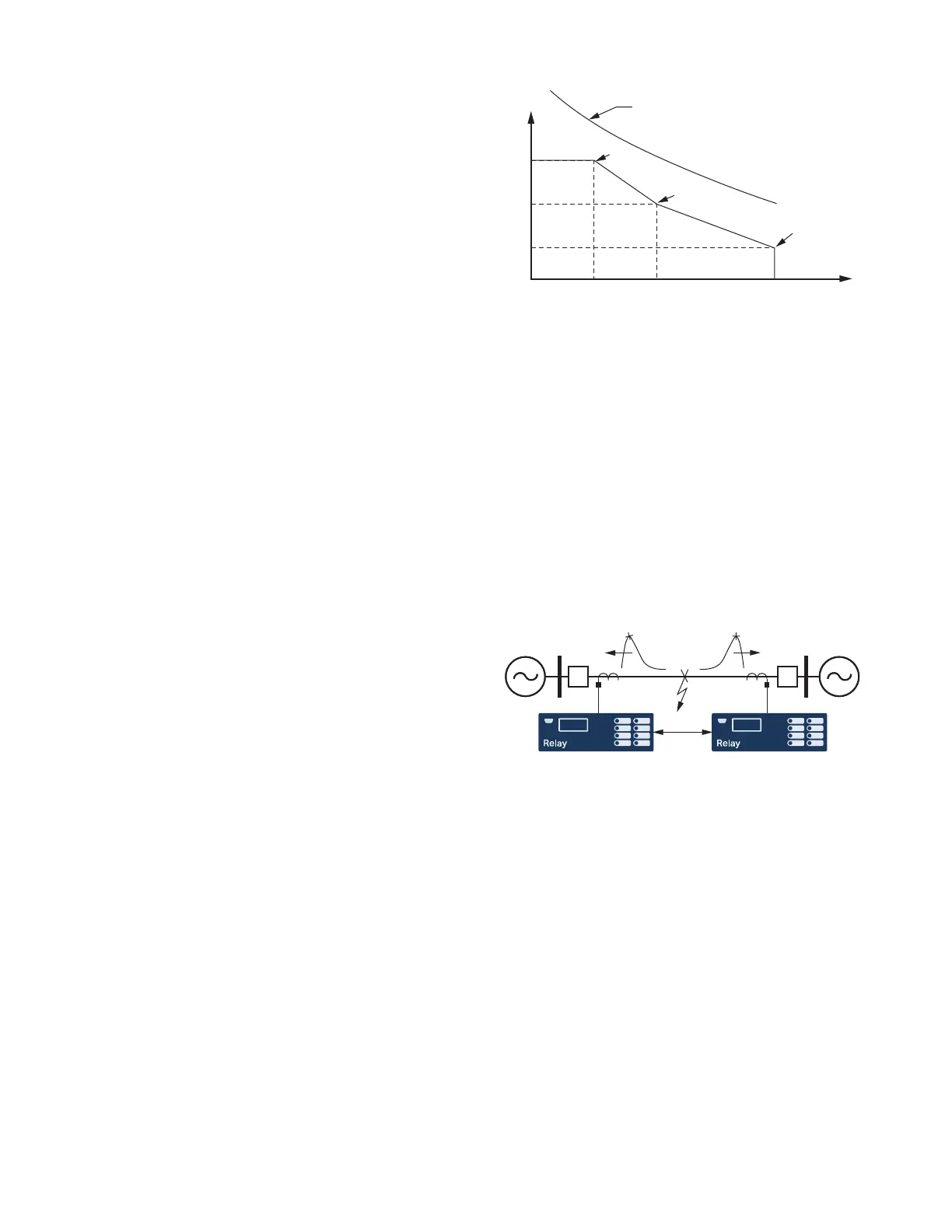
➤ Every time the breaker trips, the relay integrates
interrupted current. When the result of this integration
exceeds the threshold set by the breaker wear curve
(Figure 33), the relay can alarm via an output contact
or the optional front-panel display. With this
information, you can schedule breaker maintenance
in a timely, economical fashion.
➤ The relay monitors last and average mechanical and
electrical interruption time per pole. You can easily
determine if operating time is increasing beyond
reasonable tolerance and then schedule proactive
breaker maintenance. You can activate an alarm
point if operation time exceeds a preset value.
The relay also monitors breaker motor run time, pole dis-
crepancy, and breaker inactivity.
Traveling-Wave Fault Location
When high-accuracy IRIG-B time is available, the
SEL-411L uses a type D traveling-wave algorithm to
compute fault location. A dedicated analog-to-digital
converter samples both sets of three-phase currents con-
nected to the relay terminals (IAW, IBW, ICW, IAX,
IBX, ICX) at 1.5625 MHz. Each SEL-411L in a two-ter-
minal scheme extracts high frequency content and, based
on a setting selection, uses one set of three-phase currents
for fault location calculation. When an 87L or communi-
cations-assisted trip occurs, each relay terminal exchanges
data along with a time stamp, and the SEL-411L relays then
use this information to calculate a fault location. Figure 34
shows the traveling waves captured at each terminal.
In installations where the differential communications
channel is not available, an SEL-411L can compute fault
location manually by using the traveling-wave COM-
TRADE files it retrieves from either terminal.
The SEL-411L displays all fault location estimates (trav-
eling-wave and one impedance-based).
Figure 33 Breaker Contact Wear Curve and Settings
Figure 34 Relays Exchanging Peak Information Via 87L
Communications Channel
kA Interrupted
(Set Point 1)
(Set Point 2)
(Set Point 3)
Breaker Manufacturer's
Maintenance Curve
Close to Open Operations


 To Next Page