- 7 -
Digital Network & Power Overview
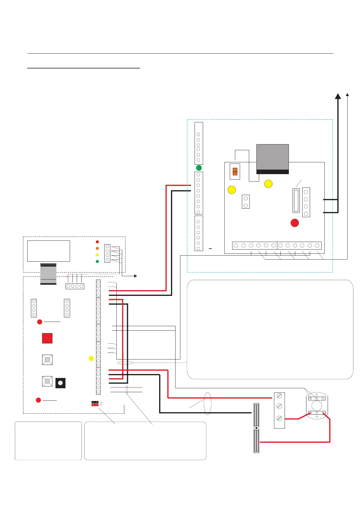
Digital Audio
Installation Manual
Pre-wired
To Panel Amplifier
+
_
1
2
Display
BUSY
FLAT CALLED
TALK NOW
ENTER
Note:
See page 24-25 for PAC connections and
jumper positions.
1
2
+VE
-VE
12V
12V
0V
pcb. 2024
Iss. 3
With DDA
facility
Vout
0V
SCN
Flat Programming
Button
Board Healthy
Indicator
12V
0V
SCN
SIG
CAM2 (Lobby)
12V
0V
SCN
SIG
CAM1(Panel)
+
_
1
2
RTE/T
LS2
PAC +
PAC -
LS1
LC
SA
SE
Stb-
Stb+
0V
CTS
SD
DMS
DMS
RTE/T
AC1
TXP
TXP
Fuse 3.15A
Anti surge
50VAC Supply Indicator
Digital Interface Board
AC1
AC2
AC2
CTS
OV
OV
TC
TC
CTS
SD
SD
2
2
1
1
Main Controller
Next Riser
Controller
0V
0V
0V
MFL+
MF
MFL-
12V
12V
12V
B+
B
TX
TX
TC+
TC-
15
16
PAC2+
PAC2 -
TR
TR
Note:
Pre-wired for 12VDC Lock Output.
If a 12VAC/DC Lock Output is required use LS1& LS2
with a secondary power Supply.
If a Volt free contact is required to trigger a PAC Controller
RTE then remove both links and use LS1 & SA for Normally
Closed and LS1 & SE for Normally Open.
This will give Volt free contacts when a Lock release is
initiated from the Telephone/Monitor or system RTE is
pressed
For Fail Secure (SE)
Lock Releases
wire N/O to RTE/T only.
Common
1
Normally
Open
4
Normally
Closed
2
RTE
N/C
N/O
Magnetic Locks
with Door Contact
Emergency Override Switch
B+C
12VDC Lock Release Output from PAC
Controller programmed to 2 seconds
Fail Safe.
If the above is required please move
both jumpers to connect pins 2 & 3
Sw1
Prog
Sw2
Up
Load
Sw3
Down
Load
Digital Entrance Panel
Door Open
Tone Control
PAC relay
Healthy Indicator
1 2 3
1 2 3
1 & 2 Jumper positions
NO PAC connected
2 & 3 Jumper positions
PAC connected
Digital Audio
Revision 1.09 Date: 05/12/2011