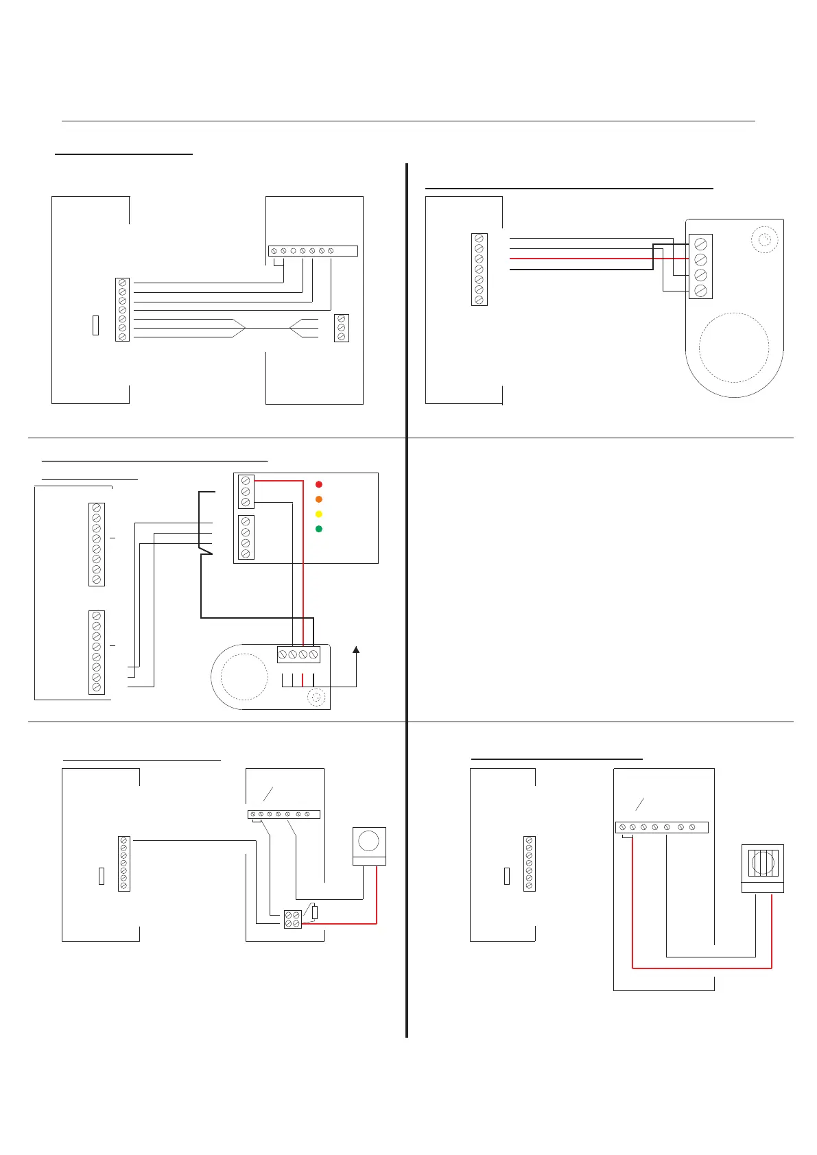
Landing Panel Amplifier wiring detail
System Controller
Amplifier (See Amplifier wiring detail)
Blue of White
White of Blue
Blue and Red Pair
White of Orange and Orange of White
1
CC
DML
SBL
2
+
-
0
PANEL 1
Strobe wiring detail
CA1 2 6 10 9
Standard call input
connection
Blue of White
Telephone Handset
1,C
2
6
9
PS
PL
DL
1,C
2
6
9
PS
PL
DL
LINE 1
Strobe
RedBlack
+
100uf
35V
System, Controller
Sounder wiring detail
System Controller
LINE 1
Note:
Please refer to the Controller Programming
Instruction sheet in the Functional &
Digital Installation Manual on how to initiate the
powering of the Strobe.
- 15 -
CA1 2 6 10 9
Standard call input
connection
Telephone Handset
Sounder
RedBlack
Digital Audio
Installation Manual
AT-PID Telephone
Privacy, Privacy On Indicator and
Door Monitoring Indicator wiring detail
1 6CA 9102
PS
PL
DL
Blue of White
White of Blue
White of Orange and Orange of White
White of Green
Green of White
Brown of White
White of Brown
System Controller AT-PID Telephone Handset
1,C
2
6
9
PS
PL
DL
LINE 1
Lock Release Button
Privacy Button
Privacy On Indicator
Door Monitoring Indicator
Entrance Panel DDA Display
wiring detail
Panel Amplifier
-
+
1
2
System Controller
1
CC
DML
SBL
FCL
2
+
PANEL 1
0
1
CC
DML
SBL
FCL
2
+
PANEL 2
0
BUSY
FLAT CALLED
TALK NOW
ENTER
_
1
SBL
FCL
DML
0V
+
Panel Amplifier
To
Controller
-
+
1
2
Intercall
Functional
Digital Audio
Revision 1.09 Date: 05/12/2011