ON ON
1 2 3 4 5 6 7 8 1 2 3 4 5 6 7 8
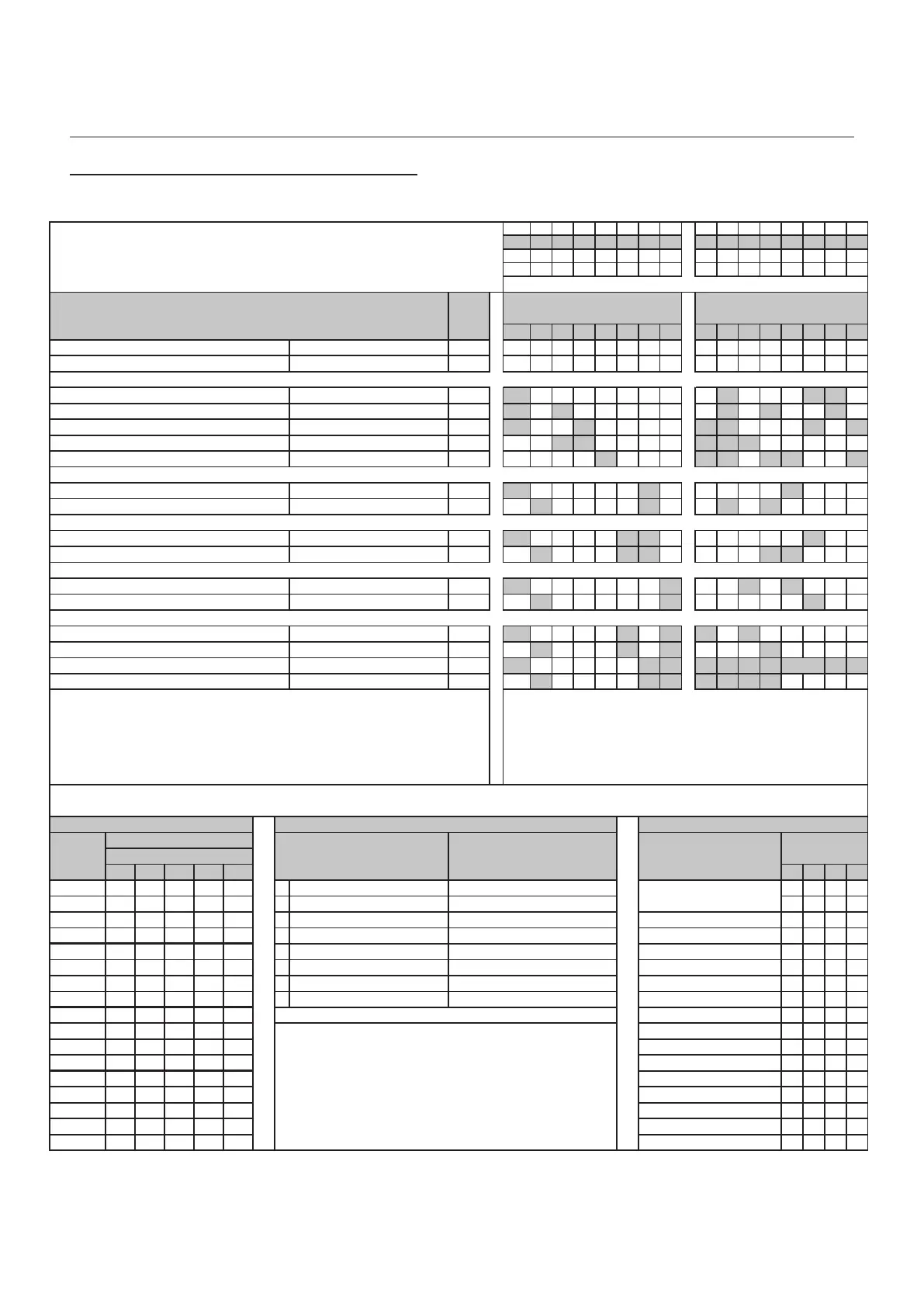
Notes
1 2 3 4 5 6 7 8 1 2 3 4 5 6 7 8
Default setting for all items 1 1 1 1 1 1 1 1 X X X X X X X X
Send setup to serial P o rt 0 0 0 0 0 1 1 1 0 0 0 0 0 0 0 X
Low Call Volume and P rivacy Time Line1-Privacy 10 M ins 1 1 0 0 0 0 0 0 0 0 1 0 0 0 1 1 0
M edium Call Volume and P rivacy Time Line5-P rivacy 50 M ins 1 1 0 1 0 0 0 0 0 0 1 0 1 0 0 1 0
No minal Call Vo lume and P rivacy Time Line9-Privacy 4 Hours+Stro be 1 1 0 0 1 0 0 0 0 1 1 0 0 0 1 0 1
High Call Volume and P rivacy Time Line12-Privacy 8 Hours 1 0 0 1 1 0 0 0 0 1 1 1 0 0 0 0 0
Buzzer and P rivacy Time Line16-Privacy 12 Hours+Stro be 1 0 0 0 0 1 0 0 0 1 1 0 1 1 0 0 1
Lock Release Time. Entrance Panel 1 16 seconds 2 1 0 0 0 0 0 1 0 0 0 0 0 1 0 0 0
Lock Release Time. Entrance Panel 2 10 Seco nds 2 0 1 0 0 0 0 1 0 0 1 0 1 0 0 0 0
Telepho ne Ring Time. Entrance P anel 1 32 Seco nds 2 1 0 0 0 0 1 1 0 0 0 0 0 0 1 0 0
Telepho ne Ring Time. Entrance P anel 2 24 Seco nds 2 0 1 0 0 0 1 1 0 0 0 0 1 1 0 0 0
Call Duration Time. Entrance Panel 1 20 Seco nds 2 1 0 0 0 0 0 0 1 0 0 1 0 1 0 0 0
Call Duration Time. Entrance Panel 2 32 Seco nds 2 0 1 0 0 0 0 0 1 0 0 0 0 0 1 0 0
Delay before Door A larm. Entrance P anel 1 5 M inutes 3 1 0 0 0 0 1 0 1 1 0 1 0 0 0 0 0
Delay before Door A larm. Entrance P anel 2 8 M inutes 3 0 1 0 0 0 1 0 1 0 1 0 1 0 0 0 0
Do o r Alarm duratio n Time. Entrance P anel 1 Co ntinuo us 4 1 0 0 0 0 0 1 1 1 1 1 1 1 1 1 1
Do o r Alarm duratio n Time. Entrance P anel 2 15 M inutes 4 0 1 0 0 0 0 1 1 1 1 1 1 1 1 0 0
Note: 1 = ON X = A ny P o sitio n
1) If an Extension So under or Strobe are required set Data switch 8 to ON. 0 = OFF S = Seconds
2) Do not set a value of zero seconds or the system will no t time out. L = Line Number (Telephone) M = M inutes
3) Set all Data switches to the OFF po sitio n if no Door A larm is required. P = P rivacy Time (Telepho ne)
4) Set all Data switches to ON if the Do o r Open A larm is to operate co ntinuously. E = Extension So under or Strobe as required (See note 1)
Line
Number 1 2 3 4 5 1 2 3 4
1 1 0 0 0 0 ON 1 NO TIM E (remains o n 0 0 0 0
2 0 1 0 0 0 ON 2 until manually switched off) - - - -
3 1 1 0 0 0
ON
4
10 Minutes 0 1 0 0
4 0 0 1 0 0
ON
8
20 Minutes 0 0 1 0
5 1 0 1 0 0
ON
16
30 Minutes 0 1 1 0
6 0 1 1 0 0 ON 32 40 Minutes 0 0 0 1
7 1 1 1 0 0 ON 64 50 Minutes 0 1 0 1
8 0 0 0 1 0 ON 128 60 Minutes 0 0 1 1
9 1 0 0 1 0 70 Minutes 0 1 1 1
10 0 1 0 1 0 2 Hours 1 0 0 0
11 1 1 0 1 0 Note: 4 Hours 1 1 0 0
12 0 0 1 1 0 1) Select the combination that adds up to the 6 Hours 1 0 1 0
13 1 0 1 1 0 required time period.(Maximum 255 Min/Seconds). 8 Hours 1 1 1 0
14 0 1 1 1 0 10 Hours 1 0 0 1
15 1 1 1 1 0 2) All switches not required m ust be in the 12 Hours 1 1 0 1
16 0 0 0 0 1 OFF position. 14 Hours 1 0 1 1
16 Hours 1 1 1 1
5
6
7
8
1
2
3
4
FUNCTION SWITCH DATA SWITCHEXAMPLE SYSTEM SETTINGS
TIME SELECTION ( M/S )LINE SELECTION ( L ) PRIVACY TIMER SELECTION ( P )
Data Switch
Function Sw itch Number of
(M)inutes or (S)econds (M)inutes and HoursData Switch
Privacy Timer
Controller Programming Example Settings
- 22 -
Digital Audio
Installation Manual
Digital Audio
Revision 1.09 Date: 05/12/2011