11
www.selema.it
Service Manual
DC 4Q A Series
Signal inputs and outputs
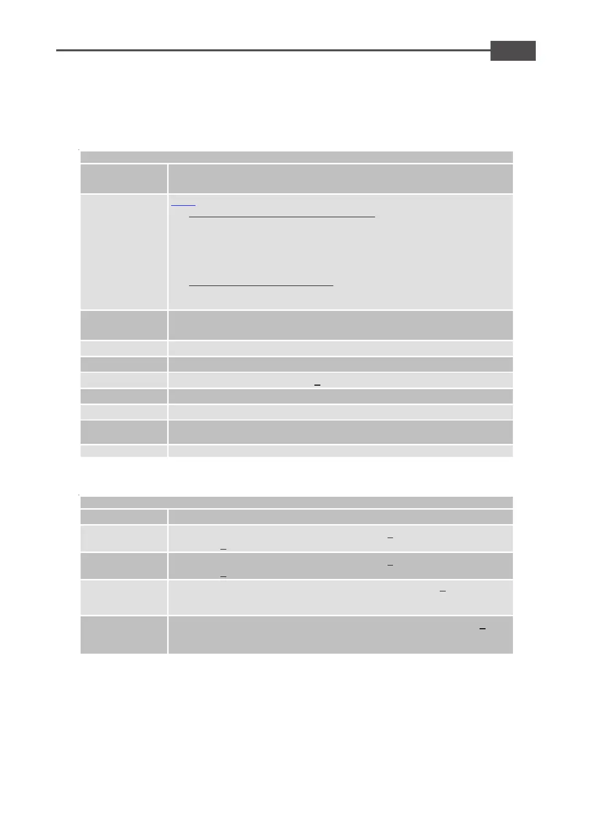
M1 CONNECTOR
1 FAULT (OUT)
Fault drive, open collector output max. 50mA
Normally closed, opens when the drive in protection mode
2 REQ
REQ:, can be used in 2 distinct modes:
1) Motor Current limit mode (by REQ setting):
A motor current limit mode connect an external resistor to GND reduces
the maximun current. Connect a 1/4W o 1/8W resistor be
REQ (pin 2) and GND (pin 3) terminals. A 47Kohm external resistor
reduces the current by 50%. (Note: The drive velocity loop remains
active)
2) Torque request (by REQ setting):
Range: +/- 10V, which corresponds to the drives peak current output. In
this mode the velocity loop is automatically disabled.
3 GND
Signal Common Ground
Corrisponds to power supply's negative GND input
4 +9.8V (OUT)
Power supply +9.8Vdc max 4mA
5 –9.8V (OUT)
Power supply –9.8Vdc max 4mA
6 START (IN)
Positive drive enable with range >+9Vdc min. to +30Vdc max
7 +VEL (IN)
Reference Positive differential input (Velocity command)
8 -VEL (IN)
Reference Negative differential input (Velocity command)
9 +TACH (IN)
Positive +DT tachogenerator input. This signals corrispond
supply's negative GND input.
10 -TACH (IN)
Negative -DT tachogenerator input.
M2 CONNECTOR
+V (OUT)
Power supply +5V max. 130mA
ENC A (IN)
Encoder input Channel A (High logic level from >
logic level <1,5V)
ENC B (IN)
Encoder input Channel B (High logic level from >
logic level <1,5V)
+L.SW (IN)
Clockwise (CW) limit Switch input. (High logic level from >
max). To enable this function, you must open the internal
and SH. See chapter 2.10
- L.SW (IN)
Counter-Clockwise (CCW) limit Switch input. (High logic level from >
To enable this function, you must open the internal soldiering
point SG and SH. See chapter 2.10