5
6"
(125mm)
7"
(175mm)
8"
(200mm)
mm
mm
mm
5"
(150mm)
mm
11 x 11
280 x 280
13 x 13
330 x 330
14 x 14
12
3
/
8
x 12
3
/
8
315 x 315
14
3
/
8
x 14
3
/
8
365 x 365
13
3
/
8
x 13
3
/
8
14
3
/
8
x 14
3
/
8
340 x 340 365 x 365
14
3
/
8
x 14
3
/
8
365 x 365
355 x 355365 x 365
14
3
/
8
x 14
3
/
8
12 x 12
305 x 305
12
3
/
8
x 12
3
/
8
315 x 315
14
3
/
8
x 14
3
/
8
365 x 365
- 15
o
, 30
o
or 45
o
Chimney Elbows (Model FC) - and suitable supports
JSC RS, or JSC ES, if required.
- Rain Cap: JSC RC or DRC - Standard or Deluxe model.
Center this first chimney section in the Ceiling Support and from
beneath the support insert the stove pipe adaptor and lock it into
place by turning clockwise until tight. This will hold your chimney
in place while the rest of your installation is completed.
Install additional chimney sections and lock together by turning
clockwise until the two sections lock together tightly. Install a
locking band to secure the two chimney sections. Continue adding
chimney lengths until a height of about 2 feet (600mm) below the
next ceiling level is achieved.
Single Story Installation
CEILING SUPPORT
To complete a proper decorator ceiling support installation, the
following parts may be required:
- Decorator Ceiling Support: JSC DCS
- Attic Insulation Shield: JSC AIS-C - Required where a chimney
passes into an unoccupied attic space.
- Firestop Radiation Shield: JSC FRS - Required where a chimney
passes from a lower living space into an upper living space or
occupied attic space.
- Roof Flashing Assembly: JSC AAF, or JFC AF2 - Required when
the chimney penetrates a roof.
INSTALLATION PROCEDURES:
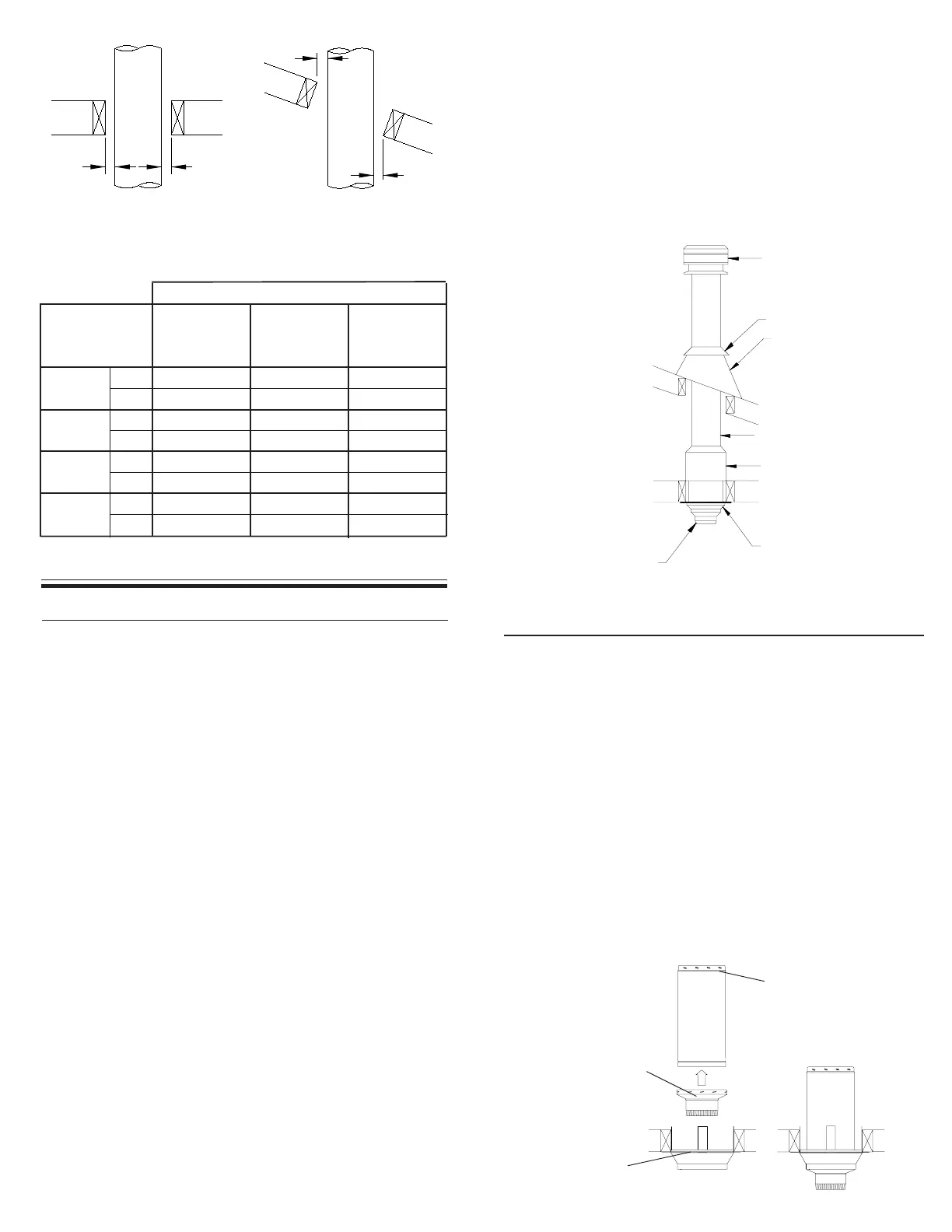
TABLE 1
Decorator
Ceiling
Support
Wall (Sup-
port)
Thimble
Framing Dimensions
All Other
Framing
Chimney Flue
Diameter
FIGURE 3
Typical Roof
Joist Framing
FIGURE 2
Typical Joist
Framing
in.
in.
in.
in.
Attic Space
Ventilated Flashing
Stove Pipe Adaptor
Storm Collar
Chimney Sections
Attic Insulation Shield
Ceiling Joist
(Framed all 4 sides)
FIGURE 4
Roof Joist
(Framed all 4 sides)
2"
(50mm)
Min
2"
(50mm)
Min
2" (50mm)
Min
2"
(50mm)
Min
Raincap
Ceiling Support
- Rafter Radiation Shield: JSC RRS - Required when the chimney
is enclosed immediately below the roof.
- Suitable lengths of Chimney (Model FC). The chimney diameter
should be sized to suit the appliance.
STOVE PIPE INSTALLATION
The Stove Pipe Adaptor (ASE) is installed by twist-locking it into the
bottom end (female end) of the first Chimney Section that enters the
Ceiling Support. Do not install an elbow in the Ceiling Support. Make
sure that the male coupler of the insulated Chimney Length is pointing
upwards as indicated by the arrow on the chimney label. Lower the
assembly down into the Support ensuring that the stovepipe adaptor
sleeve is protruding through the support and into the living space (see
Figure 5).
The crimped end (stub) of the Stove Pipe Adaptor is intended to fit
inside of the flue pipe from a solid fuel appliance, thus preventing
condensate drips at the chimney connection. In some application, the
crimped end will need to be removed as per fuel requirements and
local installation codes.
The Decorator Ceiling Support will support up to 50 feet (15.25m)
of chimney sections, all of which must be installed above the
support. Figures 4 & 5 show the 2 most common types of Decorator
Ceiling Support Installation.
Slide the Trim Ring onto the Ceiling Support and slide assembly
into framed opening from below. Ensure that the finishing plate is
flush with the underside of the ceiling and the assembly is level and
plumb. Hammer 12 6d or (2”) nails through each of the 4 straps.
Lower the first section of chimney (with the Stove Pipe Adaptor
installed on the female end) into the Ceiling Support ensuring that
the male coupler is pointing upwards, as indicated by the arrow on
the chimney label. NOTE: See next section for Stove Pipe Adaptor.
Chimney Length
Stove Pipe Adaptor
(ASE)
Decorator
Ceiling Support
FIGURE 5
Install inter-connecting flue pipe following the appliance
manufacturer's installation instructions and appropriate building
code requirements keeping in mind that the flue pipe run should be
as short and straight as proacticable. Generally, for a wood burning