9
Slide the Roof Support down over the chimney section until its
brackets rest on the roof or floor. Tighten the collar around the
chimney with the nuts and bolts supplied, then secure the collar by
screwing the 6 supplied metal screws through the holes in the collar
and into the chimney.
Center the chimney in the joist and nail or screw the support to the
roof or floor using the 12 - 3 1/2” spiral nails supplied or 12 #8 x
1 1/4 wood screws.
Install additional chimney sections and lock together by turning
clockwise until the two sections lock together tightly - continue in
this manner until the desired height is achieved.
NOTE: The male coupler of each chimney length must be up.
RAFTER RADIATION SHIELD:
A Rafter Radiation Shield must be installed where the chimney is
enclosed immediately below the roof line as shown in figure 15. An
example of this is when the attic space of a house is being used as
living space (ie. bedroom, guestroom etc.)
Attach the support brackets to the shield (through one of the three
pre-punched holes) such that once the shield is installed, the shield
protects both the upper and lower parts of the roof joist framing (See
figures 13 & 16).
Rafter Radiation Shield AssemblyFIGURE 13
Shield
Bracket
Screw
ROOF FLASHING:
Ensure that you have the proper roof flashing by checking your roof
pitch using a level and two rulers (see fig. 14) or by using a roof
pitch card.
The JSC AAF flashing is for roof pitches from Flat to 6/12.
The JSC AF2 flashing is for roof pitches from 6/12 to 12/12.
The bottom chimney length(s) should protrude into the living space
so that proper clearances are maintained on the stove pipe connec-
tor.
Install additional chimney sections and lock together by turning
clockwise until the two sections lock together tightly. Continue in
this manner until the required height above the roof is achieved.
Chimney sections (15 feet or 4.5m max.) installed below the
Cathedral Ceiling Support are locked together from below by
turning clockwise until tightly locked together with each joint being
secured by a locking band.
Cathedral Ceiling Support InstallationFIGURE 11
Storm Collar
Chimney Sections
Raincap
Ventilated Flashing
Stove Pipe Adaptor
Support Box
Support Ring
ROOF SUPPORT
The Roof Support may be used on a floor, ceiling or roof and adjusts
to any roof pitch. It may be used above an offset to support the offset
or as a supplementary support when the chimney height exceeds that
of the primary support. The Roof Support will support a total height
of 50 feet (15m) of chimney sections. All chimney sections below
the support must be secured with locking bands.
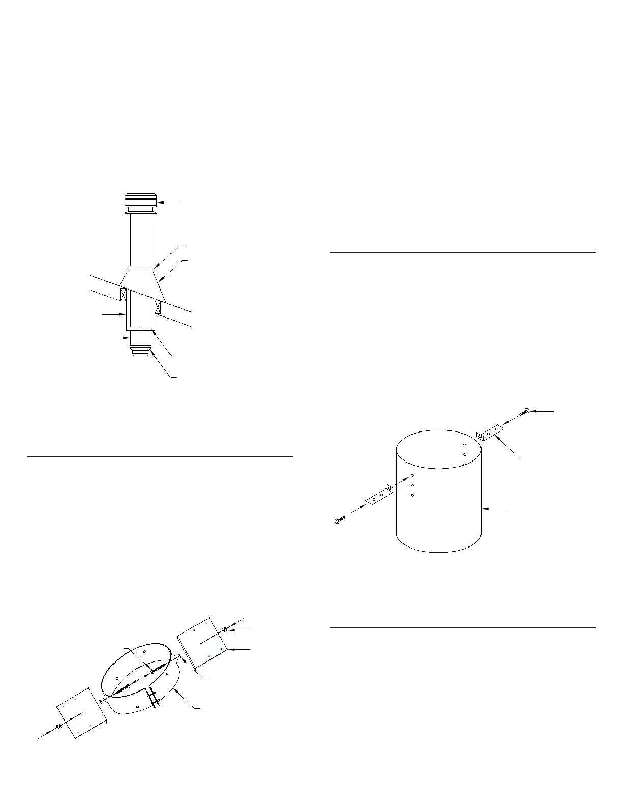
Attach the support brackets to the support band with the 1/2” nuts,
bolts and lock washers. The lock washer is placed between the band
and support bracket to provide proper spacing as shown in
Figure 12.
FIGURE 12 Roof Support Assembly
Nut
Lock Washer
Support Band
Carriage Bolt
Support
Bracket