8
Install a wall band midway up the first chimney length above the tee.
Wall bands must then be installed at a 8 foot (2.4m ) intervals above
this point. See figure 9. The nut and bolt supplied will fasten the
band around the chimney. Secure the wall band bracket to the wall
using two 6d or 2” spiral nails. For concrete walls use suitable
masonry fasteners.
If the total chimney height exceeds the wall support limitations, an
Adjustable Intermediate Wall Support JSC AIWS must be installed.
Use of an AIWS will support another 38 ft. (11.5m) of chimney.
Slide the assembled intermediate wall support over the protruding
length of chimney. Fasten the intermediate wall support to the wall
using four 1/4” by 2” wood screws through the pre-punched slots in
each bracket. Install the draw band around the protruding chimney
length securely against the support plate. Install four stainless steel
sheet metal screws firmly into the outer casing of the chimney,
through the pre-punched holes in the draw band.
After framing in your opening to the dimensions specified in the
Framing Details section, install the outer half (with square plate) of
the wall thimble in the outside wall surface. Secure in place using
appropriate fasteners using all of the pre-punched holes. For
concrete walls, cut a hole slightly larger than the chimney.
Install the inner half (with round plate) of the wall thimble in the
inside wall surface, Ensuring that the shield slides into the shield of
the outer half. Once in place and flush against the wall, install the
trim plate and fasten in place with appropriate fasteners through the
four pre-punched holes.
NOTE: To stop cold air infiltration into the dwelling you can install
the optional Universal Shielding Insulation (JUSI) into the Wall
Thimble. See separate installation instructions packaged with the
JUSI.
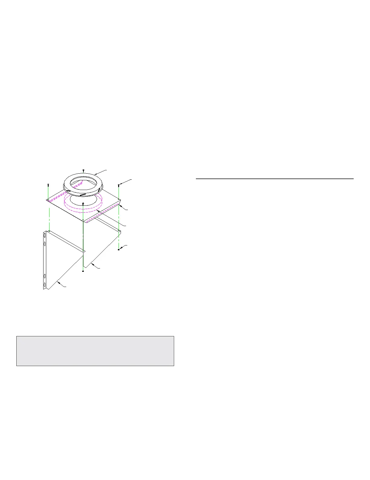
Assemble the Wall Support (Figure 10) by attaching the 2 side
brackets to the support plate, with the hardware supplied (female
coupler attached to the plate is down).
To complete a proper Cathedral Ceiling Support installation, the
following parts may be required:
- Cathedral Ceiling Support: JSC CCS.
- Roof Flashing Assembly: JSC AAF, JSC AF2
- required when the chimney penetrates a roof.
- Suitable lengths of chimney ( Model FC). The chimney diameter
should be sized to suit the appliance.
- Rain Cap: JSC RC or DRC - Standard or Deluxe model.
The Cathedral Ceiling Support will support a total of 38 feet (11.5 m),
of chimney. Chimney joints made below the support must be secured
with locking bands.
After framing in your opening to the dimensions specified in the
Framing Details section, slide the Cathedral Support box into joist
opening. Once the box is at the desired level, ensure box is level and
nail the box to framing using four 2” spiral nails or equivalent per
side. The excess material sticking above the roof can either be
trimmed off before attaching the box to the framing or, after it is
installed the corners can be cut and the excess material folded down
onto the roof deck.
Install the Support Band on the Chimney length at the desired
position by tightening the draw band bolt and by screwing four
stainless steel sheet metal screws through the draw band and into the
outer casing. Lower the chimney length down through the opening
in the bottom of the support so that the Support Band makes contact
with the bottom of the Support Box. (See Figure 11).
4 painted ceiling trim angles (2 short & 2 long) are supplied with
fastening screws to finish off the Support Box at the ceiling level.
The 2 long pieces are trimmed off to match the pitch of the ceiling.
NOTE: The male coupler of each chimney length must be up.
NOTE: To stop cold air infiltration into the dwelling you can install
the optional Universal Shielding Insulation (JUSI) into the Cathedral
Support. See separate installation instructions packaged with the
JUSI.
CATHEDRAL CEILING SUPPORT
Bolt
Support Plate
Female Coupler
(Down)
FIGURE 10
Install a one foot (or longer as required) length of insulated chimney
to the horizontal branch of the insulated tee. Lock securely into the
tee by twisting clockwise. A locking band must then be installed at
this connection. Make sure the nut and bolt are facing down to
prevent any water from collecting in the locking band.
NOTE: THE CHIMNEY MUST EXTEND AT LEAST
3” (75 MM) INTO THE LIVING SPACE WHERE THE
STOVE PIPE CONNECTOR WILL BE ATTACHED TO
THE CHIMNEY BRANCH.
From outside the building, slide the chimney length (previously
installed on a tee) through the wall thimble ensuring the male
coupling on a tee is facing upward.
Place the adapter ring (Figure 10) on the wall support so that the
sleeve on the adapter drops through the hole in the support plate.
Place the assembled wall support against the wall (plate up) directly
below the tee. Slide wall support up to the tee ensuring that the
adapter on the wall support engages with the female coupler of the
tee. Ensure the wall support is level, and secure to the wall with four
1/4” by 2” Lag Bolts through the pre-punched slots in each bracket.
If the support is properly positioned, these lag bolts will go into wall
studs placed on 16”(405mm) centers.
Adapter Ring
Nut
Side Bracket
Side Bracket
 Loading...