5
Wiring
All wiring must be performed by a suitably qualified person who is familiar with, and ensures compliance
with, the appropriate Electrical Wiring Regulations.
There is no need to use screened mains cabling.
EMC screened cable must be used to connect the controller and motor. An EMC gland must be fitted to
the motor and the preinstalled EMC Gland must be used in the controller.
All wiring that exits the controller including low voltage control cabling must be screened.
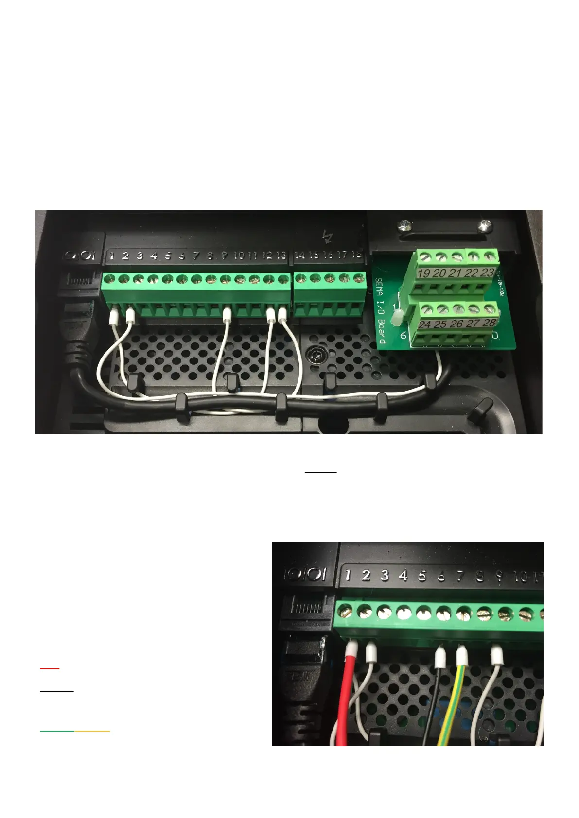
The picture above shows the control terminals of the WPC. Please note that, on some models, terminals
19 to 28 are not installed as they have no function. See page 8. The wiring and links shown in the picture
are installed by Sema and are necessary for the correct functioning of the controller. Please do not re-
move or alter any of these.
While there are other optional components
which may be wired to these terminals (see
page 8) the only additional piece of wiring
which is essential to make the unit operate is
from the transducer. Connect this as follows:
RED wire to terminal 1.
BLACK (in some cables this may be blue) wire
to terminal 6.
Green/Yellow striped (in some cables this may
have a clear covering) wire to terminal 7 or 9