12
english
Art. No.: 09/4798.214.004 © changes and errors excepted
GB
Electrical connection
The pump manufacturer's installation and operating instructions must be observed!
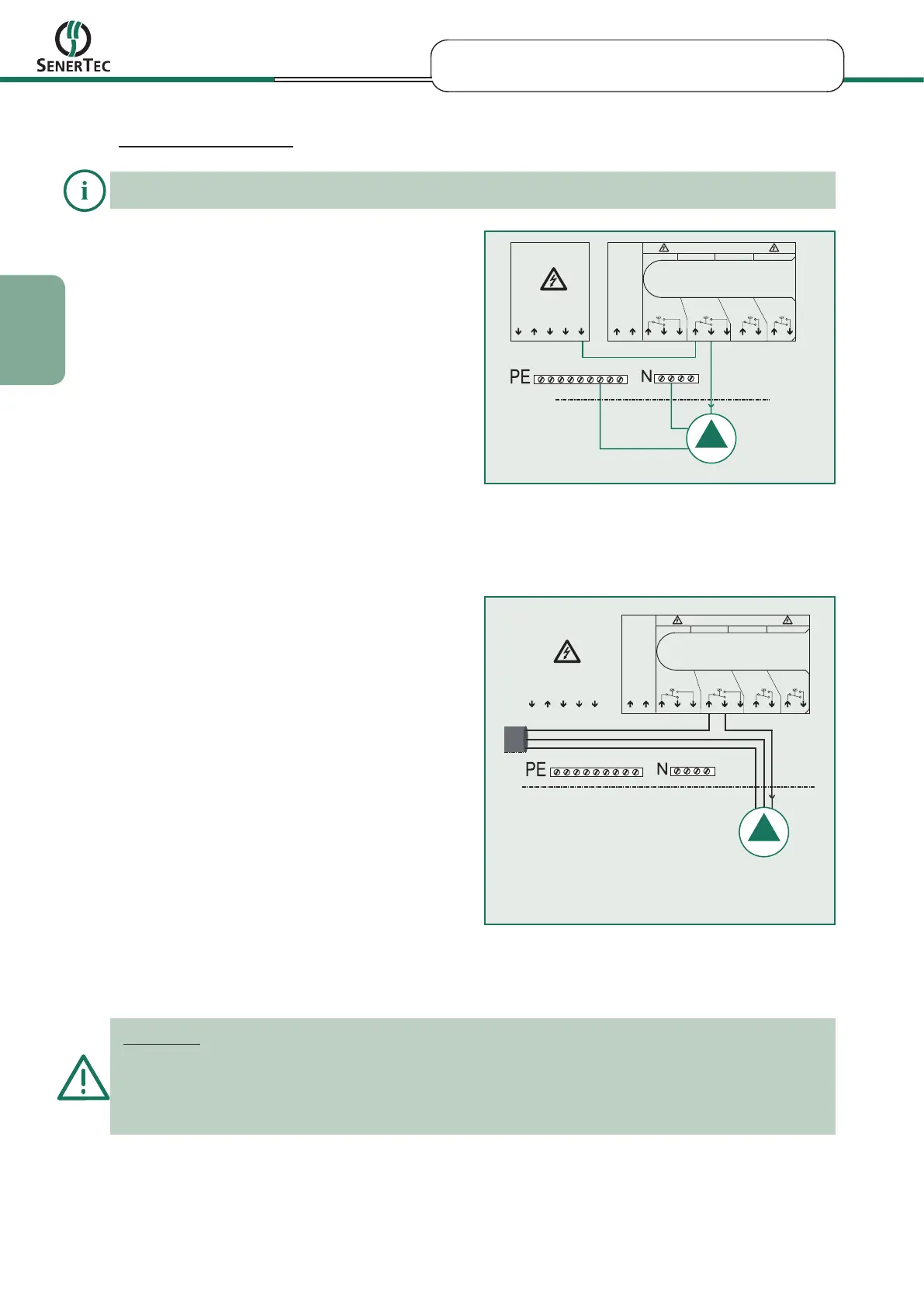
Single systems (MSR 2)
black: Controller terminal strip X6/8*
blue: Neutral terminal
green/yellow: PE terminal
* Phase L1 (Link from X5/5 to X6/6)
X5/4
X6
X5 2
30V AC
F11 4A/T F14 4A/TF13 4A/TF12 4A/T
X6/3-5
X6/6-8
X6/9-10 X6/11-12
X6/1
X6/1
X5/1
230V AC
X5/5
X5/3
X5/2
151 12
X5/4
X6
X5 2
30V AC
F11 4A/T F14 4A/TF13 4A/TF12 4A/T
X6/3-5
X6/6-8
X6/9-10 X6/11-12
X6/1
X6/1
X5/1
230V AC
X5/5
X5/3
X5/2
151 12
Figure 5: Electrical connection (MSR2) of the
thermostatic pump in single module systems
Multi-module operation (MSR 2)
Figure 6: Electrical connection (MSR2) of the
thermostatic pump(s) in multi-module systems
at
L1, M4, M7, M10
Important:
The external supply voltage is important for multi-module operation, so that the other modules can continue
to be operated while the master controller is being serviced.
If consumers are supplied with external power supply, the correct connection of the neutral conductor has
to be observed. In this case, there exist two different neutral conductors that may not be interconnected.
* in the multi-module arrangement, the power for the thermostatic pump
must be sourced externally. Switching off the controller at the main switch
would also switch off the thermostatic pump and thus prevent further
operation of the other modules, owing to overtemperature.
External power supply
PE
N
L


 To Next Page