Do you have a question about the Sennheiser EM 1031-U and is the answer not in the manual?
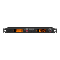
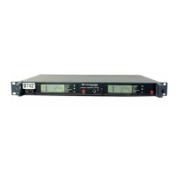
Identifies and explains the function of front panel buttons and displays (P, C, L1, L2, L3).
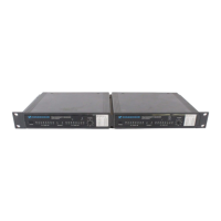
Details all input and output connectors on the rear of the unit (ANT.A, ANT.B, B1, B2, V, D).
Connects the mains unit and uses the cable grip for secure power supply.
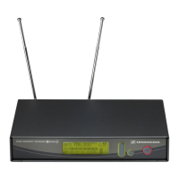
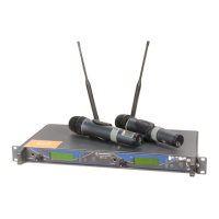
Connects antennas and explains the requirement for diversity mode.
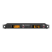
Instructions for installing the receiver in a 19-inch rack.
Ensures adequate airflow for permanent or rack installations.
Details audio output options (B1, B2) and usage guidelines, including single output use.
Steps to safely connect power and turn on the receiver.
How to select channels and ensure proper frequency synchronization.
Interpreting RF level indicators (L1) for optimal performance.
Interpreting AF level indicators (L3) for optimal performance.
Indicates the active diversity channel for optimal reception.
Guides users through identifying and fixing common operational problems.
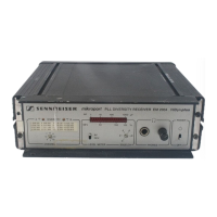
Detailed technical data including frequencies, sensitivity, and dimensions.
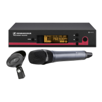
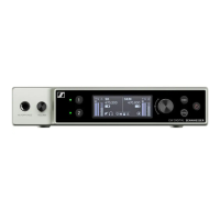
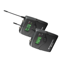
Overview of system components and available accessories.
Official approval document for telecommunications equipment.
Standard notice regarding subject to alteration and printing information.
| Modulation | FM |
|---|---|
| Total Harmonic Distortion | < 0.5% |
| Adjacent Channel Rejection | > 70 dB |
| Intermodulation Attenuation | > 70 dB |
| Blocking | > 90 dB |
| Tuning Steps | 25 kHz |
| Audio Frequency Response | 50 - 18, 000 Hz |
| RF Sensitivity | < 1 µV |
| Squelch | Adjustable |
| Audio Output Level (balanced) | +18 dBu |
| Audio Output Level (unbalanced) | +12 dBu |
| Audio Output | XLR, 6.3 mm jack |