EasyManua.ls Logo

Sennheiser EM 100 G2 User Manual

Sennheiser EM 100 G2
32 pages
To Next Page IconTo Next Page
Page #1 background imageLoading...
Page #1 background image
SA 040818
Subject to alterations
Sennheiser electronic GmbH & Co. KG • 30900 Wedemark
Phone: +49 (5130) 600 0 • Fax: +49 (5130) 600 300 1/32
EM 100 G2
EM 300 G2
EM 500 G2
Service manual
Short Description
The three stationary receivers EM 100 G2, EM 300 G2 and EM 500 G2
are
,True Diversity receivers and are equipped with the HDX noise reduction
system. Each receiver has a switching bandwidth of 36MHz in the UHF band.
Features
1440 UHF frequencies available for interference-free reception.
Direct channel selection via presets.
Scan function for finding free receive channels.
Low battery warning on transmitter and receiver.
Squelch pilot tone for interference-free operation.
Sound check mode for checking transmission conditions
(only EM 500 G2).
POWER
SET
SET
ON
300
ON
SET
500
EM 100 G2
EM 300 G2
EM 500 G2

Other manuals for Sennheiser EM 100 G2

Question and Answer IconNeed help?

Do you have a question about the Sennheiser EM 100 G2 and is the answer not in the manual?

Sennheiser EM 100 G2 Specifications

General IconGeneral
BrandSennheiser
ModelEM 100 G2
CategoryReceiver
LanguageEnglish

Summary

Short Description

Features

Safety Requirements

Controls and Indicators

Technical Data

General Specifications

Electrical and physical specifications, operating conditions, and output levels.

RF Part Specifications

Details on receiver principle, frequency ranges, bandwidth, and channel separation.

AF Part Specifications

Information on compander system, S/N ratio, AF output voltage, frequency response, and pilot tone.

Description

Mainboard Overview

Details on the mainboard's structure, functions, and signal processing.

RF Module Description

Information about the RF module's PCB, connections, and functions.

Display Module Description

Details on the display module's connection and function.

Monitor Module (EM 500 G2)

Description of the monitor module for the EM 500 G2, including its connections and operation.

Exploded View

Exploded View: EM 100 G2

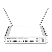
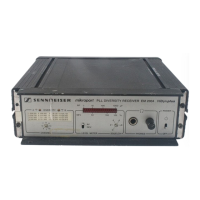
Diagram showing the assembly of the EM 100 G2 receiver.

Exploded View: EM 300 G2, EM 500 G2

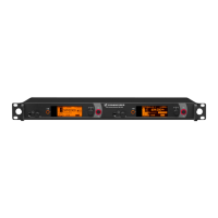
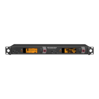
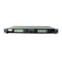
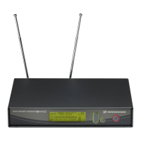
Diagram illustrating the assembly of the EM 300 G2 and EM 500 G2 receivers.

Test and Alignment Instructions

Measuring and Test Equipment

List of necessary equipment for testing and aligning the receivers.

Measuring Setup

Diagram illustrating the recommended setup for measurements and alignment.

Test Table

Table detailing test sequences, measurement points, settings, and required values.

Service Interface Data Operations

Procedures for reading/changing unit data using the DATA service interface.

Circuit Diagrams

Block Diagram

High-level functional overview of the receiver's internal architecture.

Mainboard Circuit Diagram Part 1

Detailed schematic of the mainboard, section 1 of 3.

Mainboard Circuit Diagram Part 2

Detailed schematic of the mainboard, section 2 of 3.

Mainboard Circuit Diagram Part 3

Detailed schematic of the mainboard, section 3 of 3.

RF Board Circuit Diagram Part 1

Detailed schematic of the RF board, section 1 of 3.

RF Board Circuit Diagram Part 2

Detailed schematic of the RF board, section 2 of 3.

RF Board Circuit Diagram Part 3

Detailed schematic of the RF board, section 3 of 3.

Monitoring Module MOD.A020 Circuit Diagram

Schematic diagram for the MOD.A020 monitoring module.

Interconnector Assignment

Mapping of signals between different modules and connectors.

Mainboard Component Side Layout

Layout diagram showing component placement on the mainboard's component side.

Mainboard Solder Side Layout

Layout diagram showing the solder side of the mainboard.

RF Board Component Side Layout

Layout diagram showing component placement on the RF board's component side.

RF Board Solder Side Layout

Layout diagram showing the solder side of the RF board.

Monitoring Module MOD.A020 Component Side Layout

Layout diagram of the MOD.A020 component side.

Monitoring Module MOD.A020 Solder Side Layout

Layout diagram of the MOD.A020 solder side.

Related product manuals