12
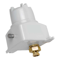
CD-20 Sample Probe Controller
Table 3.1—Troubleshooting Tips for 12VDC/24VDC Controllers
Problem Probable Cause Recommended Action
Input power fuse F1 open. Input power surge above 33VDC. Check fuse F1. Replace as
required.
Short circuit on the power board. Return to factory for
replacement of power board.
Motor Fuse F2 open. Motor stall (locked rotor). Check fuse F2. Replace as
required.
Short circuit in motor armature circuit. Return to factory for
replacement of control card.
Motor does not run and
the current limit LED is off.
Input power not on or connected backwards. Check wiring of 1TB-1 and
1TB-2 on control card.
Fuse F1 or F2 open. Check fuse continuity. Replace
fuses as required.
Open circuit to motor armature. Check wiring of 2TB-1 and
2TB-2 on power board.
CD-20 control failure. Return to factory for
replacement of control card.
Jumper E1 not connected to 1TB-3 or 1TB-4. Check jumper position.
Pulsed mode selected but no pulses of
proper amplitude at 1TB-5 to 1TB-6.
Verify the pulse input signal is
present.
Motor continues to run.
The PROX (“Hold”) LED
never comes on or blinks
on and off.
Broken or open proximity switch wire. Check wiring of 2TB-3 and
2TB-4.
The proximity switch is not sensing the high
points of the cam.
Check proximity switch and
cam alignment.
CD-20 control failure (power supply board). Return to factory for
replacement of CD-20 motor
control assembly.
Power Board Functions—115VAC and 230VAC Controllers
The CD-20 power board provides the following functions:
• Fuse F1 (1-amp, type AGC) provides short circuit protection. It will open if there is a short in the primary
or secondary of transformer T1.
– For 115VAC units, transformer T1 converts the input power to 14 VRMS secondary power when
primary jumpers W1 and W2 are installed on the power board. Note: Do not confuse these jumpers
with W1 and W2 on the control card.
– For 230VAC units, transformer T1 converts the input power to 14 VRMS secondary power when
primary jumper W3 is installed on the power board.
• Diodes CR2, CR3, CR4, and CR5 provide full-wave rectied DC voltage for use in driving the motor.
• Transistor circuits including Q1, Q2, and Q4 provide the basic speed control and drive for the CD-20 gear
motor, which has a 9VDC armature and pm eld.
• Power Fet Q3 is on when the RUN/STOP latch is commanding the motor to stop. Q3 provides electronic
braking of the motor to minimize coast past the desired probe stopping point.
• Resistor R5 is the current-sensing resistor for the current limit switch.
• Regulator U1 provides +12VDC for the control card.
 Loading...