Do you have a question about the Sensia JISKOOT InSpec Sampler and is the answer not in the manual?
Details the intended applications for the Jiskoot InSpec controller.
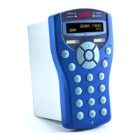
Identifies the components and layout of the InSpec controller's front panel.
Explains the primary functions of the Start, Stop, and Reset buttons.
Highlights key features like the user interface and connectivity.
Details user access levels, default users, and password management.
Describes the basic screen layout and menu navigation.
Explains different data entry methods like numeric and alphanumeric.
Defines registers and their usage for storing data.
Covers configuration options for displaying data on the front panel.
Details how to configure and manage alarms within the system.
Provides access to system-level settings like date, time, and IDs.
Explains how to generate, print, and manage reports and logs.
Provides information about the operating system and file system.
Defines the purpose and basic principles of data transfer.
Explains the difference between parallel and serial data transmission.
Details the characteristics and limitations of parallel and serial transmission.
Explains the concept of serial transmission and its requirements.
Defines communication modes: simplex, half duplex, and full duplex.
Discusses DTE/DCE terminology and cable types for RS232.
Details the RS232 serial communication standard.
Details the RS422 serial communication standard.
Details the RS485 serial communication standard.
Explains line termination and fail-safe circuit requirements.
Covers essential IP settings like addresses, masks, and gateways.
Details configuration for Network Time Protocol synchronization.
Explains how the InSpec resolves URLs to IP addresses.
Describes system configuration files and logs on the SD card.
Details the structure for storing system configuration backups.
Explains the temporary files used during operation.
Describes the organization of batch data files on the SD card.
Explains how to access the file system using FTP.
Details software updates and management via the bootloader.
Explains how to upgrade software using a testcard.
Describes the process of upgrading using an upgrade data folder.
Provides instructions for updating the bootloader software.
Introduces the Modbus protocol and its implementation.
Explains the consequences of accessing invalid Modbus addresses.
Details the configuration required for Modbus serial communication.
Covers the setup for ModbusTCP communication over Ethernet.
Defines the node number for Modbus slave identification.
Explains the different Modbus modes: ASCII, RTU, and TCP.
Describes word order options for 32-bit and 64-bit data types.
Lists the standard Modbus functions supported by the unit.
Explains how Modbus addresses are allocated and accessed.
Lists registers useful for Modbus communication.
Configures the timeout period for incomplete RTU packets.
Sets the configurable string size for Modbus.
Allows selection between 32-bit and 64-bit float accuracy.
Configures the Modbus offset for holding registers.
Details the configuration and operation of Modbus slave mode.
Explains how to configure and manage Modbus master queries.
Introduces the facility for performing simple register calculations.
Describes the different types of commands supported.
Explains the execution sequence and timing of UCL programs.
Details how to create and store UCL programs on the SD card.
Describes how to use the 'BLD' command to create UCL files.
Explains how to start and run a compiled UCL program.
Defines the components of a UCL program statement.
Explains data types and the process of type casting in UCL.
Details the arithmetic operators available in UCL.
Explains the logical operators for boolean operations in UCL.
Details the comparison operators for boolean logic.
Covers bit-wise operators for manipulating binary data.
Explains the use of shift operators for bit manipulation.
Details operators for manipulating register pointers.
Covers advanced mathematical functions available in UCL.
Explains the conditional operator for decision making.
Discusses operator precedence and the use of parentheses.
Details how to implement conditional jumps and loops in UCL.
Describes the process and formula for flow weighted averaging.
Covers the setup and configuration of PID blocks.
Explains methods for backing up instrument configuration.
Details the procedure for restoring instrument configurations.
Lists and describes options available in the system start-up menu.
Introduces the web interface for monitoring and control.
Describes the graphical schematics available via the web interface.
References the manual for Remote I/O field connections.
Explains how to connect and configure Remote I/O modules via web interface.
Details configuration, testing, and calibration of Remote ADC modules.
Details configuration, testing, and calibration of Remote DAC modules.
Explains configuration and testing for Remote Digital modules.
Details testing procedures for Remote Pulse Input modules.
Introduces the web page interface for Remote IO modules.
Refers to the InSpec Controller Safety Instructions manual (H84).
Provides general requirements for instrument installation.
Specifies suitable environmental conditions for instrument placement.
Details the procedure and tools needed for mounting the instrument.
Describes the rear connections for field signals and power supply.
References safety instructions for input power connections.
Provides guidelines for terminating shielded and screened cables.
Details how to manage cable screens and drain wires.
Describes connections for relay outputs (Installation Category III).
Details terminal assignments for serial communication ports.
Describes connections for power, digital I/O, pulse, and analogue signals.
Provides key specifications for physical, environmental, and power aspects.
Details creepage and clearance requirements for safety.
Lists relevant international standards the instrument complies with.
Provides a flowchart for dismantling the unit into its parts.
Describes the process for reassembling the instrument.
Details how to fit and remove PCBs for maintenance.
Identifies and describes the function of each PCB.
Details the configuration items on the F3174 PCB, including battery replacement.
Details configuration items on the F3175 PCB, including switch settings.
Details configuration items on the F3176 PCB, including display contrast.
Provides information on the storage life of the lithium battery.
States the expected data retention time for the controller.
Provides the expected lifespan of the LCD backlight.
Outlines essential safety precautions for maintenance work.
Provides instructions for cleaning the instrument.
Addresses common issues like power, display, and serial communication problems.
Provides contact details for technical support and service.
Lists recommended spare parts for operation and maintenance.
Provides instructions for safely packaging the unit for shipping.
Defines common abbreviations and acronyms used in the manual.
Explains the meaning of various symbols and icons used.
Provides the dimensions for the controller panel cut-out.
Guides through the process of installing the controller in a safe area unit.
Details the steps for configuring Remote I/O modules.
Contains legal information regarding warranty and liability.
| Brand | Sensia |
|---|---|
| Model | JISKOOT InSpec Sampler |
| Category | Controller |
| Language | English |