SECTION 27: PRINTED CIRCUIT BOARDS InSpec Sampler Controller
27.4 F3175 CONFIGURATION
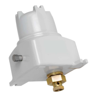
The figure below shows the location of all the configurable items on the F3175 PCB.
Figure 62 - F3175 Configurable Items
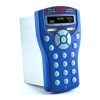
27.4.1 SWITCH SETTINGS FOR ‘SW1’
Switch SW1 allows each pulse input to be configured as either Voltage Pulse input or Current
Pulse input, as follows: -
Off = Voltage Pulse
On = Current Pulse
Off = Voltage Pulse
On = Current Pulse
Figure 63 – Pulse Input Configuration Switches
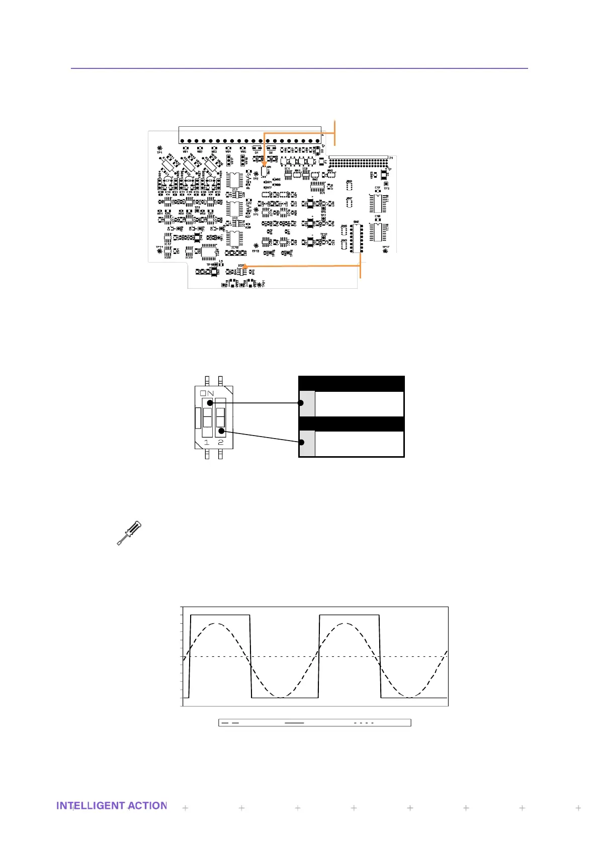
27.4.2 TRIGGER THRESHOLD ADJUSTMENT
Multi-meter (To measure 0 to 24V DC)
2.5mm Hexagon Wrench or Allen Key
1.5mm wide parallel tip screwdriver
The trigger threshold for each pulse input can be changed by the manual adjustment of a
potentiometer; accessible only by removing the front panel of the instrument.
Figure 64 - Pulse Input Trigger Threshold Operation
-0.5
0
0.5
1
1.5
2
2.5
3
3.5
4
4.5
5
5.5
Input Signal Output Signal Threshold
Pulse Inputs
V
oltage/C
urrent
Pulse
Configur
ation.
Pulse Inputs
T
rigger
threshold
adjustmen
t.
 Loading...