InSpec Sampler Controller SECTION 23: MAKING CONNECTIONS
SECTION 23: MAKING CONNECTIONS
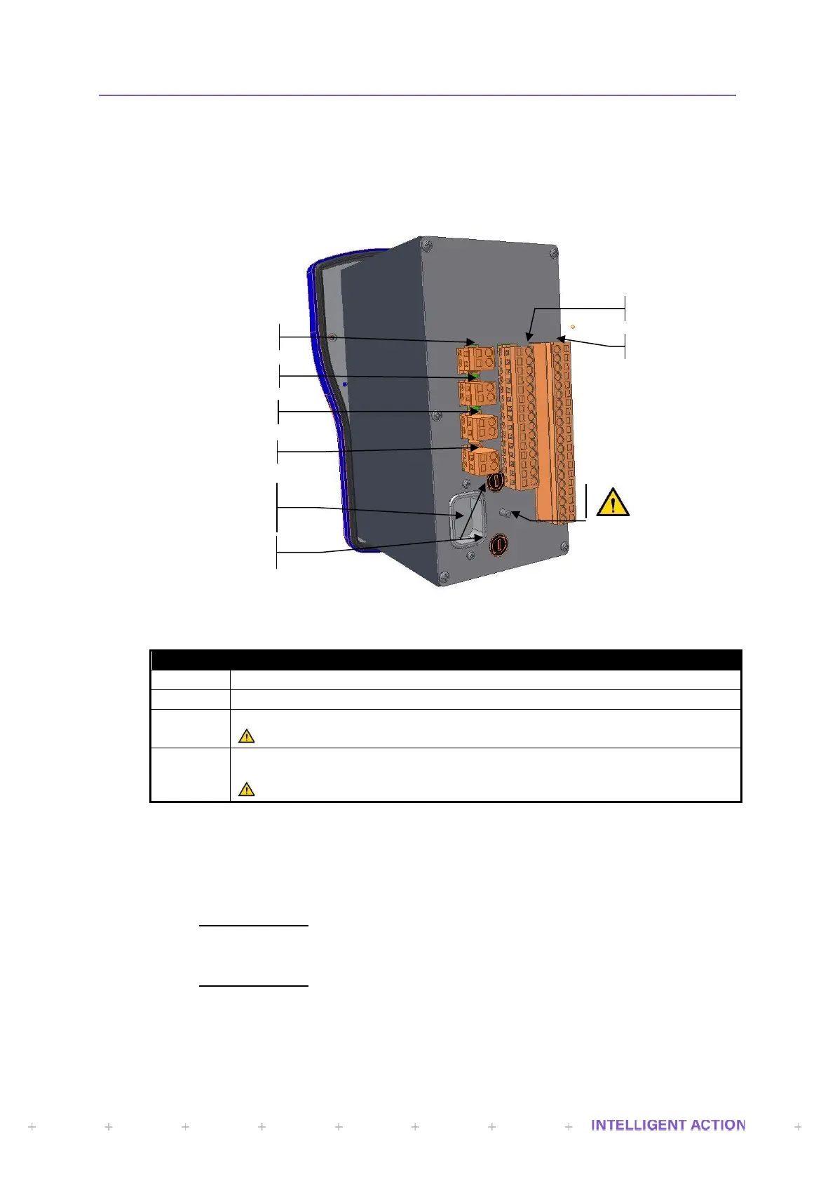
23.1 Field and Power Connections (Rear)
There are seven external connectors on the rear of the controller and full descriptions for these are
found in the sections that follow: -
Figure 45 - InSpec Rear Connections
Instrument AC Power Supply Inlet
Relay Outputs (Electromechanical)
Serial Communications Ports (RS232/RS422/RS485)
All circuits wired to Plug 5 must be connected to SELV circuits.
Analogue Inputs & Outputs, Pulse Inputs, Digital Inputs/Outputs and 24VDC
Input/Output.
All circuits wired to Plug 6 must be connected to SELV circuits.
23.2 INPUT POWER
Refer to the latest revision of the InSpec Controller Safety Instructions manual (H84).
23.2.1 EARTHING REQUIREMENTS
AC Powered Units
When the instrument is powered from an AC main supply using the IEC AC power inlet
connector, the instruments protective earth is achieved via the IEC inlet.
DC Powered Units
When the instrument is powered from a regulated 24V DC supply using Plug 6, a
protective earth (PE) conductor should be connected to the earth stud on the rear of the
instrument.
AC Power Supply
Connector
 Loading...