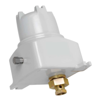
Figure 27 - Set 20mA calibration point during ADC calibration routine.
Once your input test signal settles, enter the value for the default 4mA calibration
point. On doing so you will then be presented with a very similar 20mA screen.
To calibrate between 4 and 20ma, the values entered have to be within a given range
else a message box will appear stating that the calibration is ‘Invalid’.
DAC Calibration
Using a meter, the engineer calibrates the DAC’s by reading and entering the
recorded output signals for 4 and 20mA. After entering the calibration values the user is asked
if they wish to go into the DAC test screen to check the calibrated values. The calibrate/test
cycle repeats until the user exits either routine.
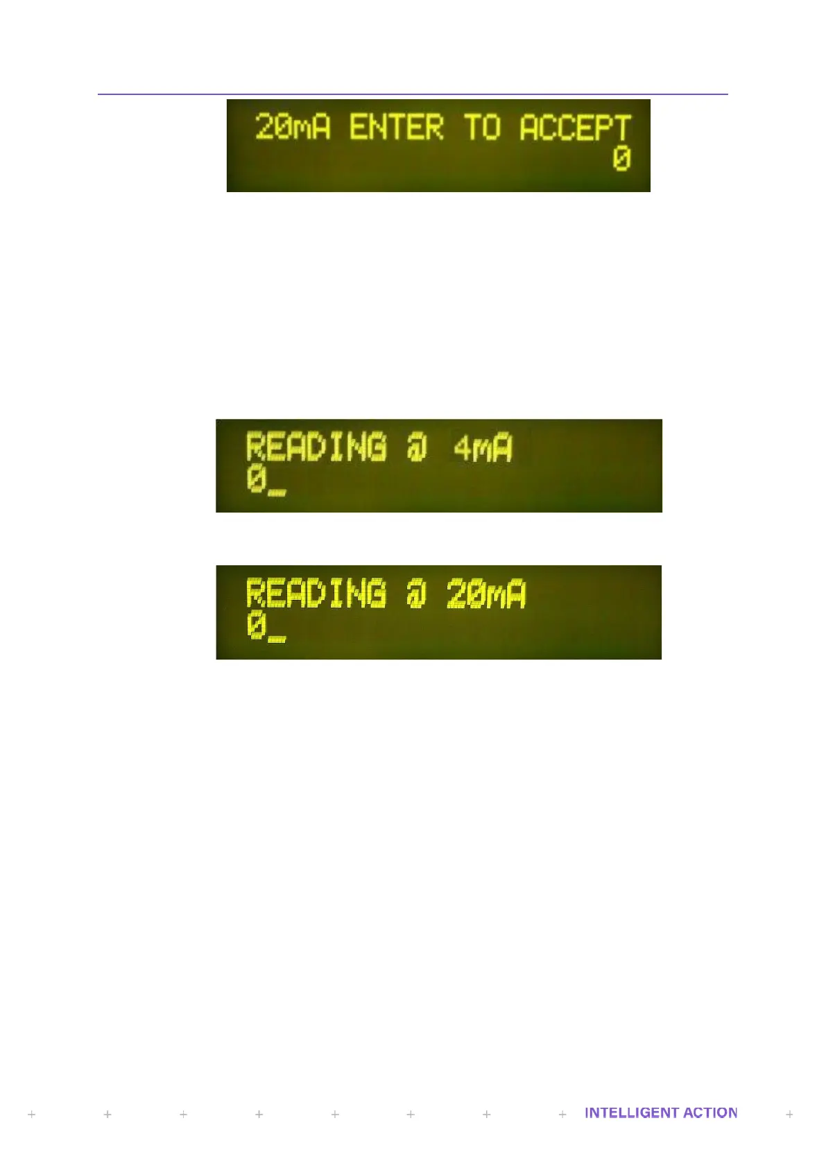
Figure 28 - Set 4mA calibration point during DAC calibration routine.
Figure 29 - Set 20mA calibration point during DAC calibration routine.
2.10 RECORDS AND LOGS
2.10.1 GENERATE REPORT
Selecting this during a batch will create an intermediate batch report. This is effectively a
snapshot of the current batch. Each intermediate report contains a numerical suffix. E.g.,
REPORT00.TXT, REPORT01.TXT, REPORT02.TXT, REPORT03.TXT etc. Note: An intermediate batch
report is also created whenever the application goes into the paused, stopped, emergency stopped or
restarting mode. The end of batch report will still be generated regardless of how many intermediate
reports are generated.
2.10.2 PRINT
Printers on an InSpec can be serial and/or Ethernet. Within the print menu of Records and
Logs, the following items are available:
BATCH REPORT
This menu item allows you to navigate to previous reports and select them for printing.
On selection you will be prompted to navigate down through the historical files that are stored
on the flash SD card. First, you will be prompted to select the year, then the month, then the
day, then the specific batch.
 Loading...