Warning:
• Instructions for adjustments while covers are removed and for servicing are for use by service
trained personnel only.
• To avoid dangerous electric shock, do not perform such adjustments or servicing unless qualified
to do so.
Modern electronic devices are very sensitive to static electric charges.
Use a grounding wrist strap at all times - See section 0 for more details
No.1 Pozidriv (cross-head) Screwdriver
2.5mm Hexagon Wrench or Allen Key
4mm Hexagon Wrench or Allen Key
7mm Combination Spanner
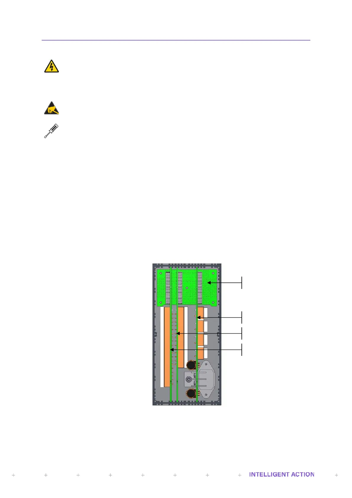
27.1 FITTING & REMOVAL
27.1.1 MAIN CASE/EXTRUSION
If any of the following operations need to be carried out on the instrument, it will be necessary to
remove one or more of the PCBs (For more information see sections 0 & 27.2): -
• Upgrade application software (Sampler or Blender Controller)
• Change communications protocol or line termination (RS232/RS422/RS485)
• Change Pulse Input configuration (Current/Voltage pulse)
• Replace battery for battery backed memory
• Replace a PCB
Figure 60 - PCB locations within the main case
27.1.2 FRONT PANEL
If the software contained within the front panel needs upgrading or the PCB requires replacing
then it will be necessary to dismantle the front panel (For more information see sections 0 & 27.2).
 Loading...