EasyManua.ls Logo

Sensia CLIF MOCK CD-20 - User Manual

Sensia CLIF MOCK CD-20
16 pages
Print Icon
To Next Page IconTo Next Page
Loading...
CLIF MOCK™
CD-20 Sample Probe Controller
User Manual
Manual No. 2350752-01, Rev
. 02
Class I Groups C and D
Hazardous Locations
Question and Answer IconNeed help?

Do you have a question about the Sensia CLIF MOCK CD-20 and is the answer not in the manual?

Summary

Safety Information

Symbols and Terms

Explains symbols and terms used in the manual for clarity and safety.

Overview of CD-20 Sample Probe Controller

CD-20 Controller Operation

Details how the CD-20 sample probe controller functions with pulse inputs and motor rotation.

Hazardous Location Compliance

Information on UL-listing and compliance for hazardous locations for controller assemblies.

Installation and Wiring Guide

CD-20 Maintenance Procedures

Performing Operational Tests

Outlines the steps for performing operational tests on the CD-20 controller.

Repeat Mode Checkout Procedure

Procedure for checking the repeat mode (time-proportional) operation of the controller.

External Pulse Mode Checkout

Procedure for checking the external pulse mode (flow-proportional) operation.

Sample Probe and Controller Checkout

Procedure for checking the sample probe and CD-20 controller integration.

Factory Repair Information

Warranty and Liability Limitations

Overview

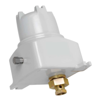
The CD-20 Sample Probe Controller, manufactured by Sensia (a joint venture of Rockwell Automation and Schlumberger), is an explosion-proof device designed for use with True-Cut C-Series sample probes. Its primary function is to control the sampling process, offering both pulse input (flow-proportional) and repeat (time-proportional) control modes. When a "start" pulse is received, the probe rotates to capture and discharge a 1.5-ml isokinetic sample. The C21 probe collects one 1.5 cc sample per 360-degree rotation, while the C22 probe collects two 1.5 cc samples per 360-degree rotation. The probe's stopping position varies based on its installation: in a horizontal line, it stops in the closed position, and in a vertical line, it stops in the open position.

Function Description:

The CD-20 controller manages the rotation of the sample probe. In repeat mode (time-proportional sampling), the controller initiates sampling at regular intervals determined by a potentiometer, which can be adjusted from 3 seconds to 3 minutes. In external pulse mode (flow-proportional sampling), the controller responds to an external pulse input. For a "start" pulse to be registered, the input must be closed for at least 5 milliseconds, or an electronic square wave input must have an amplitude of 12VDC. A 5VDC square wave will not work. Upon receiving a valid pulse, the motor rotates the probe 180 degrees to collect a sample. The motor control assembly ensures precise operation, with armature feedback controlling the motor speed to approximately 12 rpm and current feedback limiting motor current to 3 amperes. A proximity switch provides the signal to stop the motor at the correct position. Two LEDs on the control card, I-LIMIT and PROX ("Hold"), assist in monitoring the controller's operation. The I-LIMIT LED illuminates during acceleration when the drive is in current limit, while the PROX ("Hold") LED is on when the motor is stopped. The controller can also transmit a signal verifying the 180-degree rotation of the motor to a control room if desired.

Important Technical Specifications:

The CD-20 controller is available in different power configurations: 12VDC, 24VDC, 115VAC, and 230VAC.

  • Temperature Range: -40°C to 55°C for all models.
  • Voltage:
    • 24VDC model: 24VDC @ 2A max.
    • 115/230VAC model: 115/230VAC @ 1A max.
  • Pulse Input: 12VDC for all models.
  • Transistor Output: 12VDC max @ 100mA max for all models.
  • Current Draw (Controller):
    • Stop Mode: 30 mA (24VDC), 60 mA (115/230VAC).
    • Running Mode: 0.5 Amp (24VDC), 150 mA (115/230VAC).
    • Peak Motor (Turn On) Current: 1 Amp (24VDC), 300 mA (115/230VAC).
  • Current Draw (Motor):
    • Motor (Turn On) Current: 320 mA (24VDC), 850 mA (115/230VAC).
  • Motor: DC gear motor with a gear ratio of 150:1.
  • Housing: Explosion-proof, with two ¾-in. NPT holes for line power and input pulse, and a ½-in. breather plug and a ½-in. conduit plug.
  • Hazardous Location Safety Compliance: Assemblies designed for 24VDC, 115VAC, and 230VAC input power are UL-listed in the US and Canada for Class I Groups C and D Hazardous Locations. The 12VDC controller is available without UL listing.

Usage Features:

  • Direct Mounting: The CD-20 controller mounts directly to the C-Series sample probe using a DC-2 coupling, eliminating the need for additional brackets or supports, although they are recommended for piping with significant vibration.
  • Configurable Sampling Modes: Users can select between time-proportional (repeat mode) and flow-proportional (external pulse mode) sampling by configuring an on-board jumper (E1) on the control card.
  • External Power Output: A +12VDC output at 1TB-7 is available to power external flow pulse circuits, such as turbine meter pre-amplifiers, with a maximum current of 50 mA.
  • Motor Rotation Verification: The transistor output contact (1TB-8 and 1TB-9) can be connected to a control room to verify motor rotation, with jumpers W1 and W2 allowing configuration of whether the transistor turns on or off when the proximity switch is opposite the high point on the cam.
  • Diagnostic LEDs: The I-LIMIT and PROX ("Hold") LEDs provide visual feedback on the motor's operational status, aiding in troubleshooting and monitoring.

Maintenance Features:

  • Operational Test Procedure: A comprehensive start-up procedure is provided, including repeat-mode checkout, external input pulse mode checkout, and sample probe/control drive checkout. This requires a push-button switch, a power supply, and a 100-ml graduated beaker.
  • Troubleshooting Tips: Detailed troubleshooting tables are provided for both 12VDC/24VDC and 115VAC/230VAC controllers, outlining probable causes and recommended actions for common issues such as input power fuse open, motor not running, motor continuously running, and current limit LED issues.
  • Modular Design: The motor control assembly consists of a control card and power board, facilitating easier diagnosis and replacement of components.
  • Fuse Protection: The power boards incorporate fuses (F1 and F2) for short circuit and over-current protection, which are user-serviceable.
  • Factory Repairs: To maintain UL certification, repairs must be performed by a UL-authorized Cameron facility. Instructions are provided for returning products for repair, including contact information for requesting a Return to Manufacturer Authorization (RMA) form.
  • Motor Armature Leads: If the motor rotation direction is incorrect, the motor armature leads at 2TB-1 and 2TB-2 can be swapped.

Sensia CLIF MOCK CD-20 Specifications

General IconGeneral
BrandSensia
ModelCLIF MOCK CD-20
CategoryController
LanguageEnglish

Related product manuals