10
CD-20 Sample Probe Controller
Repeat Mode (Time-Proportional) Check-Out
The repeat time potentiometer (Figure 2.3), which determines the rate of sampling when the controller is
connected to a probe, is typically set at the factory at 15 seconds. However, it can be adjusted over a range of
3 seconds to 3 minutes.
To perform the repeat mode check-out,
1. Connect jumper E1 to terminal 1TB-4 (Figure 2.2, page 8).
2. Apply input power to the CD-20 control card. Input power will be 12VDC, 24VDC, 115VAC or 230VAC,
depending on the controller model purchased.
3. Verify that the motor rotates 180 degrees and stops. This should take approximately 2.5 seconds. The pro-
cess should repeat at regular intervals as determined by the potentiometer (off delay) setting.
Note—Any input pulses that occur when the CD-20SFA is rotating are disregarded by the control logic.
4. Verify that the PROX (“Hold”) LED is on while the motor is stopped.The PROX (“Hold”) LED should be
off while the motor is running and turn on when the motor stops.
5. Verify the I-LIMIT LED blinks on momentarily during acceleration of the CD-20 motor. After the motor
reaches the 12 RPM running speed, the I-LIMIT LED should turn off.
6. Verify the CD-20 output shaft rotates in a clockwise direction as you look at the shaft from the bottom of
the CD20. The sample probe will rotate counterclockwise when the CD-20 controller is connected. If the
direction of motor rotation is wrong, swap the motor armature leads at 2TB-1 and 2TB-2.
External Pulse Mode (Flow-Proportional) Check-Out
1. Disconnect the input power from the CD-20.
2. Move the E1 jumper to 1TB-3 to select the external pulse input mode (Figure 2.2, page 8).
3. Connect a push-button switch to 1TB-5 and 1TB-6.
4. Apply power to the CD-20 control card.
5. Activate the switch to generate a pulse input to the motor control assembly. To be registered by the con-
trol logic, the input pulse must have a duration of 5 msec or longer and it must occur when the CD-20 mo-
tor is stopped and the PROX (“Hold”) LED is on.
6. Verify the CD-20 output shaft rotates 180 degrees for each external pulse.
Note—Any input pulses that occur when the CD-20 is rotating are disregarded by the control logic.
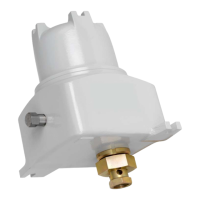
Sample Probe and CD-20 Check-Out
1. Disconnect input power from the CD-20.
2. Mount the CD-20 to the sample probe and hand-tighten the DC-2 coupling.
3. Make sure the push-button switch is still connected to 1TB-5 and 1TB-6.
4. Verify that the product line is full and pressurized.
 Loading...