7
CD-20 Sample Probe Controller
Table 1.1—CD-20 Specications
24 VDC 115/230 VAC
Temperature -40ºC to 55ºC -40ºC to 55ºC
Voltage 24VDC @2A max 115 / 230 VAC @ 1A max
Pulse Input 12VDC 12VDC
Transistor Output 12VDC max @ 100mA max 12VDC max @ 100mA max
Current Draw (Controller)
Stop Mode
30 mA 60 mA
Running Mode
0.5 Amp 150 mA
Peak Motor (Turn On) Current
1 Amp 300 mA
Current Draw (Motor)
Motor (Turn On) Current
320 mA 850 mA
Section 2—Installation and Wiring
!
WARNING: This module is designed for connection to hazardous electric voltages. Ignoring
this warning can result in severe personal injury or mechanical damage. This product must
be reliably earthed and installed by qualied personnel in accordance with the prevailing local
electrical wiring regulations and safety standards.
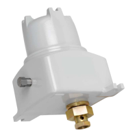
The CD-20 controller mounts directly to the C-Series sample probe via the DC-2 coupling (Figure 2.1). The
DC-2 coupling should be hand-tightened to ensure that the internal retaining ring is not pushed out of its
groove. If the DC-2 coupling is over-tightened at the CD-20 hub, the motor shaft will not engage the DC-1
coupling on the probe.
Figure 2.1—DC-2 coupling
All eld connections are made to terminal block 1TB on the control card (Figure 2.2). Install wiring as
follows:
1. Connect power to 1TB-1 and 1TB-2.
2. Connect the ow pulse input contact to 1TB-5 and 1TB-6. If an open collector transistor driver is used,
connect the collector to 1TB-5 and connect the emitter to 1TB-6 (common).
 Loading...