6
CD-20 Sample Probe Controller
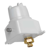
The motor control assembly (Figure 1.2) consists of a control card and power board mounted to a ring, which
in turn, is mounted to the back of the CD-20 gear motor. All eld connections are to terminal block 1TB on
the control card. The motor and proximity switch connections are made at the factory to terminal block 2TB
on the power board.
CD20 Power Board
(2TB)
CD20 Control Card
(1TB)
Figure 1.2—CD-20 motor control assembly
How It Works
When an input pulse from either the repeat-mode timer or an external pulse source is received, a command
is output to rotate the motor. Armature feedback controls the speed of the motor at about 12 rpm and current
feedback limits motor current to 3 amperes.
Time-proportional sampling may be congured for a sampling frequency of 3 seconds to 3 minutes.
Flow-proportional sampling requires that the pulse input be closed for at least 5 msec to produce a “start”
pulse. An electronic square wave input must have an amplitude of 12VDC.
The proximity switch input amplier provides the signal to stop the motor. Two LEDs installed on the
controller card allow the user to test the controller’s operation. The I-LIMIT LED is on when the drive is in
current limit, which is normal during acceleration.The PROX (“Hold”) LED is on when the motor is stopped.
Field wiring instructions are provided in Section 2—Installation and Wiring, page 7. A signal verifying the
180-degree rotation of the motor can be transmitted to a control room if desired.
Hazardous Location Safety Compliance
Assemblies designed for 24VDC, 115VAC and 230VAC input power are UL-listed in the US and Canada for
Class I Groups C and D Hazardous Locations.
A 12VDC controller is available without the UL listing.
 Loading...