InSpec Sampler Controller SECTION 24: FIELD CONNECTIONS
SECTION 24: FIELD CONNECTIONS
SELV Circuits
All circuits wired to Plugs 5 & 6 must be connected to SELV circuits.
Please refer to section 0 for a definition of SELV circuits
Circuits TBTS
Tous les circuits câblés aux fiches 5 & 6 doivent être reliés à des circuits TBTS.
Veuillez vous référer à la section 0 source de référence pas trouvé pour une définition des circuits
TBTS.
24.1 CABLE SCREENS & DRAIN WIRES
Please refer to Section 23.3.
To eliminate earth loops screens and drain wires should be left unconnected and taped back at one end.
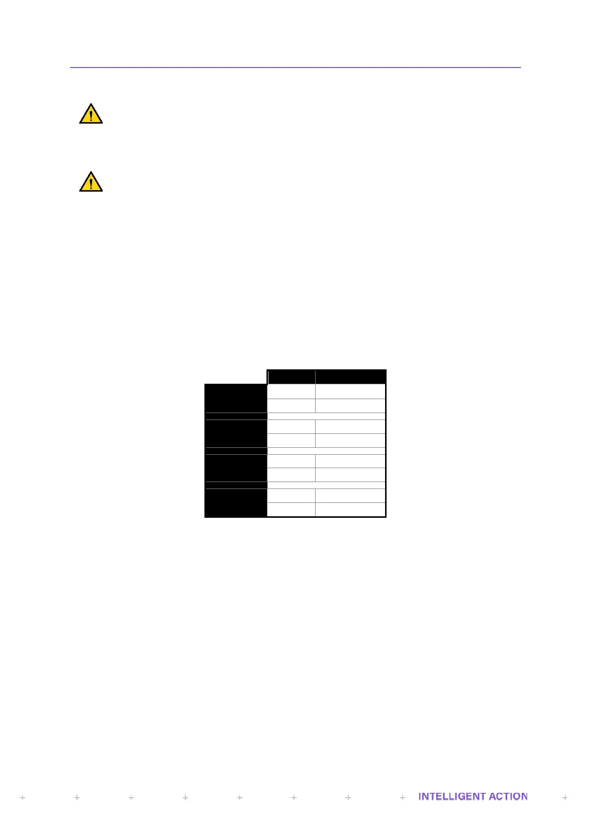
24.2 PLUG NO’S 1, 2, 3 & 4
These plugs provide connections to the relay outputs that can switch circuits designated as Installation
Category III.
Terminal assignments are as follows: -
Figure 46 - Plugs 1 to 4 Relay Connections
Insulation Coordination: -
24.2.1 RELAY OUTPUTS (4 OFF)
Each relay output is rated to switch a 2 Amp resistive load.
All wiring connected to any relay output must have a suitably sized protection device
fitted to protect the relay circuit and load being switched by it. Relay outputs are fitted with a
varistor, for suppression of voltage spikes that may be generated during switching, to extend the
life of the relay contacts.
 Loading...