Do you have a question about the Sensia NUFLO Scanner 1140G and is the answer not in the manual?
Defines limits and exclusions for product warranties.
Lists changes made to the manual over time.
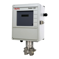
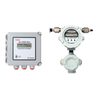
Provides a general description of the Scanner 1140 RTU.
Details the different Scanner 1140 models and available software.
A step-by-step sequence for initial Scanner 1140 installation.
Specifies temperature and static electricity handling requirements.
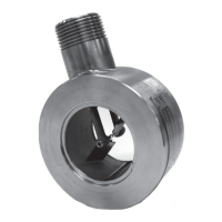
Procedures for unpacking, mounting options, and piping connections.
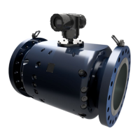
Illustrates the physical installation for the 1140T model.
Shows installation for 1140C/L with integrated communication.
Depicts installation setup for remote communication configurations.
Details how to connect power and available power supply configurations.
Explains how to update the Scanner 1140's firmware.
Describes the function and use of the optional configuration lock switch.
Outlines the initial steps required before flashing firmware.
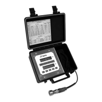
Instructions for using the ScanFlash software for firmware updates.
Guide to updating firmware using the WinsLoad utility in Windows.
Instructions for updating firmware using ScanLoad in a DOS environment.
Steps to initiate the Scanner 1140 after installation or configuration changes.
Procedure for performing a superboot to reset configuration and data.
Identifies key components on the Scanner 1140 main circuit board.
Illustrates the wiring connections for the main board components.
Describes terminal connections for field wiring and signal assignments.
Provides a summary of the functions of various DIP switches.
Details the functions and settings of the system control DIP switch SW4.
Explains the operation of the Superboot and Lithium Battery switches.
Wiring and configuration for 4-20 mA analog transmitters.
Wiring and configuration for 1-5 Vdc analog transmitters.
Information on the optional analog output feature.
Configuration settings for frequency pulse inputs via DIP switch.
Introduction to the MIO1 multi-function I/O expansion board.
Technical specifications for the MIO1 board's serial, analog, and pulse I/O.
How to terminate I/O connections on expansion boards.
Details on switches for serial port, pulse input, and analog output configuration.
Specific switch settings for various pulse input modes.
Visual guides for wiring different MIO1 expansion board configurations.
List of essential tools for diagnosing Scanner 1140 issues.
A guide to identifying and resolving common Scanner 1140 operational issues.
Step-by-step guide for replacing the NVRAM lithium battery.
Instructions for shipping the Scanner 1140 for repair or service.
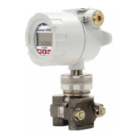
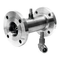
General introduction to DPE+ transducer installation.
Detailed steps for swapping an existing DPE with a DPE+ transducer.
Describes gasket installation for different enclosure types.
Instructions for installing the intrinsically safe barrier adapter.
Describes the software applications supported by the Scanner 1140.
Explains the functionality of the audit trail and event logging system.
Details the role and components of the CPU.
Explains FLASH, RAM, and NVRAM memory in the Scanner 1140.
Describes the function of the FPGA in system logic and I/O.
How vital configuration data is protected from unauthorized changes.
Details the system clocks and their timing functions.
Explains power saving features and battery choices.
Describes the 2-line x 16-character LCD display and its interface.
How the autoscroll function on the front panel works.
Provides overall operating parameters and classifications.
Details operating temperature, enclosure ratings, and humidity limits.
Lists the main components of the system board.
Information about the CPU, memory, and voltage.
A summary of the input/output capabilities of the system board.
Describes the interface for adding expansion boards.
Details on display types, functions, and character formats.
Information on the serial ports, baud rates, and protocols.
Describes the digital I/O channels and their functions.
Technical specifications for RTD inputs.
Details on accuracy, impedance, and resolution for analog inputs.
Specifications for the optional pulse input board.
Specifications for the optional analog output board.
Accuracy specifications for differential pressure measurements.
Accuracy specifications for static pressure measurements.
Pressure ranges and bolt types for DPE+ transducers.
Details on the transmitter power supply output voltage and current.
Information on how power supplies support RTU operation and battery recharging.
Details for the 6V rechargeable battery system.
Information on the non-rechargeable alkaline battery option.
Details for using an external DC power source.
Details for the 12V rechargeable battery system.
Describes the software supported by the Scanner 1140 for various measurements.
Physical dimensions of the Scanner 1140T front view.
Physical dimensions of the Scanner 1140T side views.
Physical dimensions of the Scanner 1140C front view.
Physical dimensions for Scanner 1140C endcap mount.
Physical dimensions for Scanner 1140C universal mount.
Physical dimensions of the Scanner 1140G top view.
Physical dimensions of the Scanner 1140L front view.
Physical dimensions of the Scanner 1140L enclosure side view.
List of part numbers and descriptions for the Scanner 1140T model.
List of part numbers and descriptions for the Scanner 1140C model.
Index of installation drawings for Division 1 and Division 2 configurations.
Installation diagram for Division 1 hazardous areas.
Barrier rating configurations for Division 1 installations.
Power supply wiring diagram for Division 1 installations.
Wiring for RS-232C serial ports in Division 1 installations.
Wiring for status and pulse I/O in Division 1 installations.
Wiring for RTD and analog inputs/outputs in Division 1.
Wiring diagram for analog outputs in Division 1 installations.
Wiring diagram for MVX inputs in Division 1 installations.
Installation diagram for Division 2 non-hazardous areas.
Power supply wiring diagram for Division 2 installations.
Wiring for serial ports in Division 2 installations.
Wiring for status and pulse I/O in Division 2 installations.
Wiring for RTD and analog inputs/outputs in Division 2.
Wiring diagram for analog outputs in Division 2 installations.
Wiring diagram for MVX inputs in Division 2 installations.
| Display | LCD |
|---|---|
| Power Source | Battery |
| Response Time | 1 second |
| Application | Gas flow measurement |
| Output | 4-20 mA |