Do you have a question about the Sensia NuFlo and is the answer not in the manual?
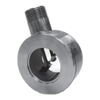
Diagram illustrating the key components of the NuFlo gas flowmeter.
Explanation of how the turbine flowmeter measures gas velocity and volume.
Guidance on the proper installation of the NuFlo gas flowmeter in a pipeline.
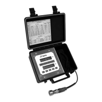
Procedures for calibrating the electronic readout using factory calibration factors.
Steps to convert actual cubic feet to standard cubic feet using factors.
Assessment of how pressure variations impact gas volume measurement accuracy.
Step-by-step instructions for safely removing and installing replacement cartridges.
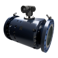
Information on different styles of NuFlo gas flowmeter assemblies available for various flow rates.
List of recommended spare parts available for the NuFlo 2-in. Gas Flowmeter.
Details on available accessories, including installation hardware kits and flow straighteners.
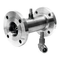
The Sensia NUFLO 2-inch Gas Flowmeter is a turbine flowmeter designed for measuring gas flow in various applications. It is housed within an insert element that is installed between two raised-face flanges in a pipeline. The design allows for continuous stud bolts to draw the flanges together, with gaskets on the face of the flanges and the meter body ensuring a secure seal. An optional hardware installation kit, including bolts, nuts, and gaskets, is available for convenience.
The primary function of the NUFLO 2-inch Gas Flowmeter is to accurately measure the volume of gas flowing through a pipeline. It operates on the principle of a turbine flowmeter, where gas impinges against the pitched blades of a rotor, causing it to spin. The rotational speed of the rotor is directly proportional to the velocity of the gas stream. As the rotor spins, its blades interrupt a magnetic field generated by an electromagnetic pickup, which is screwed into a receptacle on the side of the meter. This interruption induces a voltage pulse in the pickup's coil. A readout instrument then senses these voltage pulses and converts them into a usable form that indicates the gas volume.
The meter is designed to provide a consistent number of pulses per actual cubic foot (acf) of gas, regardless of the gas pressure and temperature, within its rated operating range. This characteristic simplifies calibration, as the calibration factor can be specified in pulses per actual cubic foot.
The NUFLO 2-inch Gas Flowmeter is designed for straightforward installation and operation. Proper installation is crucial to prevent gas swirling or other erratic flow characteristics that could affect measurement accuracy. The manual provides guidelines for typical in-line gas turbine meter installation, recommending a minimum upstream pipe length of 10 nominal pipe diameters. If a flow straightener is not used, longer upstream pipe lengths may be required to minimize measurement uncertainty due to swirl or asymmetrical flow.
The device measures compressible fluid, and its volumetric readings are affected by temperature and pressure changes. The manual provides detailed instructions and formulas for calculating gas volume in both actual cubic feet (acf) and standard cubic feet (scf). This includes considerations for absolute pressure and temperature, with atmospheric pressure typically considered 14.73 psi and absolute temperature expressed in degrees Rankine (Flowing gas temperature in °F + 459.67).
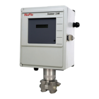
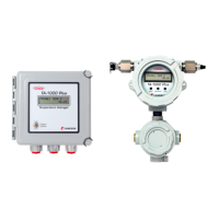
Calibration of electronic readout equipment is a key usage feature. Each flowmeter is pre-calibrated at the factory across multiple points within its flow range, and a calibration factor (pulses per acf) is provided on a tag attached to the meter. This factor is then used to calibrate field electronic readout equipment. The manual explains how to calculate gas volume in standard cubic feet, which is often preferred over actual cubic feet, especially at standard conditions (0 psi and 60°F). It also details how to determine the divisor for readout equipment to directly display measurements in standard cubic feet, particularly when flowing conditions remain constant.
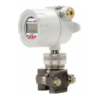
The manual also addresses the effects of fluctuating temperatures and pressures on readout accuracy. While small temperature changes might not cause significant errors, extreme variations may necessitate seasonal recalibration of readout equipment. Fluctuating pressures, however, can lead to larger errors in standard cubic feet measurements, especially at low flowing temperatures. To mitigate this, users can either sense the pressure on the flowline and correct the output with a pressure-compensated readout or a computer, or control the pressure to keep it constant using a pressure regulator downstream of the flowmeter.
The flowmeter is available with three different cartridges to accommodate high, standard, and low flow ranges, allowing users to select the appropriate configuration for their specific application needs.
Maintenance of the NUFLO 2-inch Gas Flowmeter is designed to be minimal due to its cartridge-based internal components. All internal parts, including the rotor and shaft assembly, bearings, and setscrews, are contained within a single cartridge. This design allows for easy and quick replacement of the internal cartridge in the field should the flowmeter fail.
The procedure for removing and replacing cartridges is clearly outlined:
The manual also provides tables for ordering information, including part numbers for complete flowmeter assemblies (low, standard, and high flow ranges), spare parts (cartridges for different ranges, magnetic pickup, centering rings, pickup adapter extensions, and retaining rings), and accessories (installation hardware kits for various flange ratings and flow straighteners in different pipe schedules and materials). This comprehensive listing facilitates easy identification and procurement of necessary components for maintenance and installation.
| Power Supply | 24 VDC or 100-240 VAC |
|---|---|
| Communication Protocol | HART |
| Operating Temperature | -40°C to +60°C |
| Output | 4-20 mA, pulse, frequency |
| Sensor Type | Ultrasonic |