September 2009 5
Section 1
Introduction
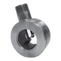
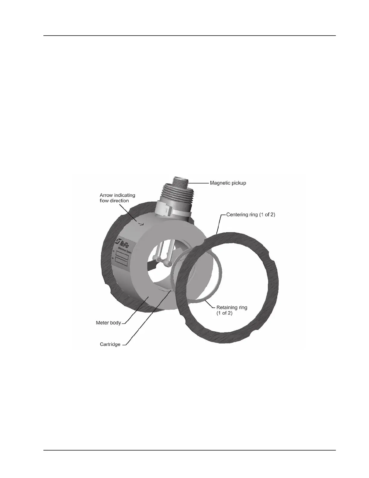
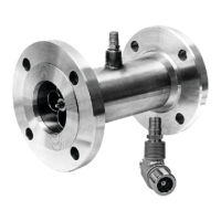
The NuFlo 2-in. Gas Flowmeter is a turbine owmeter, housed inside an insert element that is placed between
two raised-face anges. Continuous stud bolts draw the anges together against the housing element, and
gaskets on the face of the anges and meter body help ensure a competent seal. Bolts, nuts, and gaskets are
available as part of an optional hardware installation kit.
All internal components—the rotor and shaft assembly, bearings, and setscrews—are contained within a car-
tridge inside the meter. Three different cartridges are available to accommodate high, standard, and low ow
ranges (see Figs. 1.2 through 1.4, pages 3 through 5).
An electromagnetic pickup screwed into the receptacle on the side of the meter produces the output signal.
Figure 1.1—Flowmeter components
Operating Principles
The gas to be measured is owed through the meter. As the gas passes the rotor, it impinges against the
pitched rotor blade, causing the rotor to spin at a speed directly proportional to the velocity of the gas stream.
As the rotor spins, its blades interrupt the magnetic eld set up by the pickup. This interruption induces a
voltage in the coil of the pickup. The readout instrument senses this voltage pulse and converts it into a usable
form that indicates gas volume.