EasyManua.ls Logo

Sensia CALDON SVM 289Ci User Manual

Sensia CALDON SVM 289Ci
59 pages
To Next Page IconTo Next Page
Page #1 background imageLoading...
Page #1 background image
CALDON SVM 289Ci
Self-Verifying Ultrasonic Meter with G3
Transmitter
User Manual
MA23102, Rev. 01

Table of Contents

Questions and Answers:

Sensia CALDON SVM 289Ci Specifications

General IconGeneral
BrandSensia
ModelCALDON SVM 289Ci
CategoryMeasuring Instruments
LanguageEnglish

Summary

IMPORTANT SAFETY INFORMATION

SYMBOLS AND TERMS

Defines safety symbols and terms used in the document.

CONTACT SENSIA

Contact information for technical support and inquiries.

PUBLISHER NOTES

SECURITY NOTICE FOR SOFTWARE PRODUCTS

Guidelines for secure operation of software components.

Section 1: Introduction

1.1 EQUIPMENT DESCRIPTION

Overview of the CALDON SVM 289Ci ultrasonic flowmeter and its capabilities.

1.1.1 SVM 289Ci METER BODY

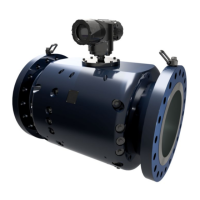
Details the components and function of the meter body, including transducers and RTD.

1.1.2 G3 TRANSMITTER

Describes the transmitter's functions, display, inputs/outputs, and communication options.

1.2 MODEL NUMBERS

Explains the structure and coding for meter body and transmitter model numbers.

1.2.1 METER BODY MODEL NUMBER

Details how to interpret the meter body model code for configuration.

1.2.2 TRANSMITTER MODEL NUMBER

Details the transmitter model number structure and various options.

1.2.3 TRANSMITTER SPECIFICATIONS

Lists technical specifications for the transmitter, including material, dimensions, and power.

1.2.4 METER MARKINGS

Describes the markings and labels on the meter body, including approvals and serial numbers.

Section 2: Meter Body Installation

1.1 LIFTING/HOISTING THE METER BODY

Procedures for safely lifting and handling the meter body using hoist rings.

2.1.1 HOIST RING INSTALLATION

Instructions for installing Sensia swivel hoist rings into meter body end flanges.

2.1.2 SLING ATTACHMENT

Guidelines for attaching slings to hoist rings for proper and safe lifting.

2.2 METER INSTALLATION

Recommendations for installing the flowmeter in the pipeline for optimal performance.

Section 3: Transmitter Connections

3.1 TRANSMITTER INSTALLATION PROCEDURE

Steps for installing the transmitter, including location and wiring considerations.

3.1.1 TRANSMITTER LOCATION

Guidance on selecting the optimal location for the transmitter based on power source distance.

3.1.2 TRANSMITTER TERMINATIONS

Details on connecting wires to the transmitter's terminal blocks, including conduit seals.

3.2 WIRING INSTRUCTIONS

General instructions for wiring the transmitter's power, I/O, and communication interfaces.

3.2.1 POWER TERMINATIONS (TERMINAL BLOCK 1)

Wiring details for DC and AC power input to terminal block 1.

3.2.2 USER 1 AND USER 2 INPUTS/OUTPUTS

Describes the galvanically isolated User 1 and User 2 input/output groups.

3.2.3 ANALOG INPUTS (TERMINAL BLOCK 2)

Configuration and wiring for analog inputs on terminal block 2.

3.2.4 ANALOG OUTPUTS (TERMINAL BLOCK 2)

Configuration and wiring for analog outputs on terminal block 2.

3.2.5 OPTIONAL HART (TERMINAL BLOCK 2)

How to connect the optional HART communication to analog output 2 terminals.

3.2.6 DIGITAL OUTPUTS (TERMINAL BLOCK 2)

Details on digital outputs, including pulse outputs and status signals.

3.2.7 GROUNDING

Instructions for proper grounding of the transmitter, including earth and isolated grounds.

3.2.8 REMOTE DATA COMMUNICATIONS

Information on Ethernet and serial communication setup and connections.

3.2.9 SERIAL COMMUNICATIONS

Wiring and configuration for serial communication ports (COM1, COM2, COM3).

3.3 METER INSTALLATION CHECK-OUT

Procedure to verify correct installation of the meter and transmitter.

3.3.1 OUTPUT TEST MODE

How to use the output test mode for field testing and verification.

Section 4: Understanding Flow Calculations

4.1 MEASURING FLOW VELOCITIES

Explains the principles of measuring flow velocities using ultrasonic transit time.

4.2 MEASURING FLOW RATE

Describes how flow rate is calculated using SVM technology and chordal planes.

4.2.1 TEMPERATURE COMPENSATION

How the meter compensates for pipe thermal expansion using internal temperature.

4.2.2 CONVERSION TO STANDARD CONDITIONS

Process for converting measured flow to standard conditions using correction factors.

Section 5: Operations

5.1 DEFINITIONS

Defines key terms like Chord, Plane, and Path used in operations.

5.2 NORMAL OPERATING CONDITIONS

Describes the expected behavior and indicators during normal operation.

5.3 DISPLAY LEDS

Explains the status indications provided by the transmitter's LEDs (Power, Operation).

5.4 DISPLAY

Details the LCD display content, various screens, and parameter readouts.

5.5 ALARM CONDITIONS

Details the automatic fault detection system and alarm notifications.

Section 6: Maintenance

6.1 INTRODUCTION

Overview of maintenance and troubleshooting procedures for qualified personnel.

6.2 GENERAL INSPECTIONS AND PREVENTATIVE MAINTENANCE PROCEDURES

Routine inspection and maintenance tasks for enclosures and internal electronics.

6.2.1 ELECTRONIC ENCLOSURE INSPECTION

Procedures for inspecting the transmitter enclosure, gaskets, and mounting.

6.2.2 INTERNAL ELECTRONICS INSPECTION

Steps for inspecting internal electronic components, cable entries, and connections.

6.3 TRANSMITTER TROUBLESHOOTING

Steps to diagnose and resolve transmitter issues by checking LEDs, power, and communications.

6.4 CIRCUIT BOARD REPLACEMENT

Information on replacing internal circuit boards like IOP, CTC, and MXR.

6.4.1 IOP – INPUT/OUTPUT AND POWER SUPPLY BOARD OR POWER FUSE REPLACEMENT

Detailed procedure for replacing the IOP board or its fuse.

6.4.2 CTC AND DISPLAY REPLACEMENT

Steps for replacing the CTC and display assembly, including handling precautions.

6.4.3 MXR REPLACEMENT

Procedure for replacing the MXR assembly, including daughter board.

6.5 TRANSDUCER INSTALLATION

Guidelines for installing or replacing transducers, including safety warnings.

6.6 ANALOG INPUT VERIFICATION

How to verify the analog input signal and understand scaling behavior.

6.7 ANALOG OUTPUT AND PULSE OUTPUT VERIFICATION

Verifying analog and pulse output signals using software functions.

6.7.1 FORCE OUTPUT (ANALOG)

Using software to force analog output for testing scaling and site devices.

6.7.2 FORCE OUTPUT (PULSE)

Using software to force pulse output for testing and verification.

Section 7: Troubleshooting and Diagnostics

7.1 DIAGNOSTICS

Accessing and interpreting diagnostic information via transmitter display and software.

7.1.1 AUTOMATIC FAULT DETECTION

How the system detects and reports faults automatically based on path data quality.

7.1.1.1. Path Status

Interpreting individual path status codes (e.g., Invalid, Pre-Valid) for troubleshooting.

7.1.1.2. Reprogramming the Transmitter

Procedure to reprogram the transmitter with its configuration file using USM Advisor.

Section 8: Metrological Seals

Section 9: Recommended Spare Parts

Related product manuals