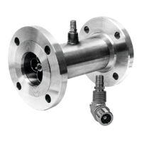
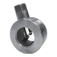
EasyManua.ls Logo

Sensia Barton 7000 Series - User Manual

Sensia Barton 7000 Series
36 pages
Print Icon
To Next Page IconTo Next Page
Loading...
Barton
®
7000 Series
Turbine Flowmeters
71xx, 72xx, & 73xx for Liquid
74xx for Gas
CE marked meters conform
to the European Union
Pressurized Equipment
Directive (PED), 97/23/EC
User Manual
Part No. 9A-11350, Rev. 04
August 2012
Table of Contents
Safety Information ............................................................................................ 2
Section 1—Introduction .................................................................................... 3
Barton 7000 Series Flowmeters.................................................................... 3
Specications—7000 Series Turbine Flowmeters ........................................ 3
Electrical Classication.............................................................................. 3
Pressure Boundary Certication................................................................ 4
Measurement Performance ....................................................................... 4
Specications—Standard Pickup Coil ...................................................... 5
CE Markings (for PED owmeters only) ....................................................... 5
Section 2—Installation and Operation .............................................................. 7
Unpacking ..................................................................................................... 7
Unpacking Procedure ................................................................................ 7
Best Practices for Installation........................................................................ 9
Filtration..................................................................................................... 9
Electrical Installation.................................................................................. 9
Flowmeter Position .................................................................................... 9
Flowmeter Location ................................................................................. 10
Bolt Size/Torque Requirements ............................................................... 12
System Pressure .................................................................................... 13
Installation Procedure ................................................................................. 13
Section 3—Maintenance ................................................................................ 17
Routine Maintenance Checklist .................................................................. 17
Parts Replacement ..................................................................................... 18
Repair Kits .................................................................................................. 18
Disassembly/Assembly ............................................................................... 21
Model 7100 Fractional-Sized Flowmeters ............................................... 21
Model 7100/7300 Flowmeters (1 in. and larger)...................................... 22
Model 7200/7400 Flowmeters ................................................................. 24
Electrical Pickup Coil Check ....................................................................... 25
Troubleshooting .......................................................................................... 25
Section 4—Dimensional Drawings ................................................................. 29

Questions and Answers

  • L
    Lucas ColemanAug 7, 2025
    What to do if Sensia Measuring Instruments show no output?
    • S
      Shaun RangelAug 7, 2025
      If your Sensia Measuring Instruments aren't showing any output, there are several potential causes to investigate: * **Electrical Connections:** Begin by checking the electrical cable connections to ensure they are correct and secure. Correct them if necessary. * **Flow Verification:** Confirm that there is flow through the pipe. * **Pickup Coil:** Test the pickup coil for continuity between the pins and replace it if it's defective. * **Rotor Inspection:** Remove the meter and check if the rotor spins freely. Replace the rotor if it's frozen. Also, inspect bearings, bearing surfaces, wear washers, spacers, diffuser, and rotor hub for foreign material or wear. Clean and reassemble if no wear is found; replace worn parts and recalibrate if wear is present.
  • J
    Jeffrey WarrenAug 14, 2025
    How to fix fluid delivery greater than indicated on totalizer in Sensia Measuring Instruments?
    • R
      ronald48Aug 14, 2025
      If the fluid delivery is greater than indicated on the totalizer for your Sensia Measuring Instruments, it could be due to: * **Foreign Material:** Remove the meter and inspect it internally for foreign material on the rotor or bearings. Remove any foreign material found. If none is found, disassemble the meter, clean the parts, and reassemble and reinstall the meter. * **Bearing Wear:** If cleaning doesn't solve the problem, it may be due to excessive bearing wear. Replace the meter internals with a repair kit.
  • G
    Gloria JohnsonAug 22, 2025
    What to do if Sensia Measuring Instruments have fluid delivery less than indicated on totalizer?
    • A
      Angela NealAug 22, 2025
      If your Sensia Measuring Instruments are showing fluid delivery that is less than indicated on the totalizer, there are a few possible causes: * **Gasification:** The liquid in the meter might be undergoing gasification. To resolve this, provide back pressure at the meter. * **Entrained Gas/Bubbles:** There might be entrained gas or bubbles in the metered liquid. Eliminate these by using an air eliminator or another acceptable method.
  • L
    lmunozAug 30, 2025
    Why Sensia Measuring Instruments output is erratic?
    • R
      Rebecca WillisAug 30, 2025
      An erratic output from Sensia Measuring Instruments may be caused by sensitivity, noise, or foreign material disturbing the fluid profile through the meter. To address this, verify the proper sensitivity setting of the electronic readout instrument, remove any intermittent noise signals, and inspect the flow straighteners for foreign material after removing the meter from the line. Also, inspect the rotor for broken blades and check the meter run for the proper length of upstream and downstream straight pipe installation.

Summary

Safety Information

Section 1-Introduction

Barton 7000 Series Flowmeters

Overview of Barton 7000 Series turbine flowmeters and their design features.

Specifications-7000 Series Turbine Flowmeters

Details electrical classification and pressure boundary certification for the flowmeters.

Specifications-Standard Pickup Coil

Lists electrical specifications for the standard pickup coil used with the flowmeters.

CE Markings (for PED flowmeters only)

Outlines markings required for flowmeters conforming to the European Union Pressure Equipment Directive.

Section 2-Installation and Operation

Unpacking

Procedures and checks for safely unpacking the turbine flowmeter upon arrival.

Best Practices for Installation

Guidance on optimal installation methods including filtration, electrical, and physical placement.

Flowmeter Position

Discusses the recommended and satisfactory operating positions for the turbine flowmeter.

Flowmeter Location

Advice on selecting the best physical location for the flowmeter to ensure accuracy and longevity.

Bolt Size;Torque Requirements

Specifies recommended bolt sizes and torque values for flange connections according to ASME standards.

System Pressure

Details considerations for maximum and minimum system pressures when installing the turbine meter.

Installation Procedure

Step-by-step instructions for properly installing the turbine flowmeter into the piping system.

Section 3-Maintenance

Routine Maintenance Checklist

Steps for performing regular inspection and maintenance on the turbine flowmeter.

Parts Replacement

Lists recommended spare parts, including pickup coils and connectors, with part numbers.

Repair Kits

Information on available repair kits for internal components and their calibration requirements.

Disassembly;Assembly

Procedures for taking apart and putting back together various Barton 7000 Series flowmeter models.

Electrical Pickup Coil Check

Method for testing the pickup coil using an ohmmeter and oscilloscope for proper function.

Troubleshooting

Guides on diagnosing and resolving common malfunctions related to electrical, electronic, or mechanical issues.

Section 4-Dimensional Drawings

Table 4.1-150# ANSI Dimensions

Provides dimensional data for 150# ANSI flanged turbine flowmeters.

Table 4.2-300# ANSI Dimensions

Details dimensional specifications for 300# ANSI flanged turbine flowmeters.

Table 4.3-600# ANSI Dimensions

Lists dimensional data for 600# ANSI flanged turbine flowmeters.

Table 4.4-900# ANSI Dimensions

Provides dimensional specifications for 900# ANSI flanged turbine flowmeters.

Table 4.5-1500# ANSI Dimensions

Details dimensional data for 1500# ANSI flanged turbine flowmeters.

Table 4.6-2500# ANSI Dimensions

Lists dimensional specifications for 2500# ANSI flanged turbine flowmeters.

Product Warranty

Warranty

Cameron's warranty statement for products shipped, covering defects in material and workmanship.

Warranty Adjustment

Procedures for notifying Cameron of defects and the process for repair or replacement.

Exclusions from Warranty

Lists conditions and circumstances under which the warranty does not apply.

Product Brand

Identifies Barton® as a registered trademark of Sensia.

Sensia Barton 7000 Series Specifications

General IconGeneral
BrandSensia
ModelBarton 7000 Series
CategoryMeasuring Instruments
LanguageEnglish

Related product manuals