10
Section 2 Model 7000 Series Turbine Flowmeter
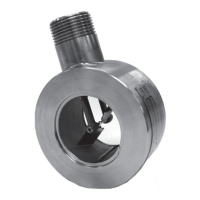
Flowmeter Location
See Figure 2.1 for reference. Location of the owmeter to obtain optimum
accuracy is dependent upon several factors.
• Relative to the System—When the ow is expected to be intermittent, the
meter should not be mounted at a low point in the piping system since
solids can settle on, or congeal around the rotor. These solids can cause
the rotor to freeze or otherwise be damaged.
• Tolerance to Mechanical Vibration—The turbine meter is constructed
to withstand rugged service. However, meter life can be increased by
locating the meter so as to protect it from the direct shock or mechanical
vibration.
• Tolerance to Electrical Interference—To obtain the best electrical signal
output from the meter, locate the meter at a distance from sources of elec-
trical interference. A preamplier is recommended for use on all installa-
tions to reduce the effect of undesired noise.
• Where practical, install the meter upstream of control valves and pres-
sure regulators. Where necessary, the meter should be at least 100 pipe
diameters from the valves.
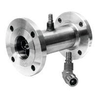
Model 7400 owmeters feature a pressure tap on the body opposite the rotor.
For compliance with international measurement standards, any pressure sen-
sor used for computation of corrected volume should sense pressure from this
tap.
 Loading...