Do you have a question about the Sensia NuFlo Scanner 2000 and is the answer not in the manual?
Measures and computes standard volumes of gas, steam, petroleum, and generic liquids.
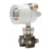
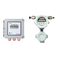
Describes the Scanner 2000's enclosure, components, power source, and inputs.
Lists available options like communication adapters, pole-mount kits, and terminal housing.
Explains device labeling, SIRA certification, and safety markings.
Details initial configuration steps using software or keypad.
Describes basic parameter configuration via keypad and ModWorX Pro software.
Outlines Fieldbus configuration using a customer-supplied tool.
Lists technical specifications for the Scanner 2000.
Details calculations for natural gas, steam, and liquid flow.
Specifies accuracy and performance of the Multi-Variable Transmitter.
Describes safe installation in FISCO intrinsically safe installations.
Explains the two-tier structure of a Foundation™ fieldbus control system.
Details compliance and precautions for hazardous environments.
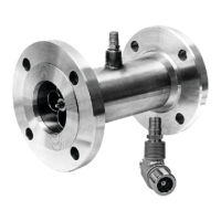
Describes direct, remote, and pole-mount installation methods.
Installation guidelines for natural gas measurement with DP meters.
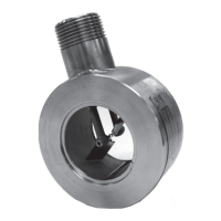
Step-by-step guide for direct mounting to orifice or cone meters.
Step-by-step guide for remote mounting to orifice or cone meters.
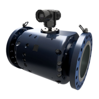
Installation guidelines for natural gas measurement with turbine meters.
Best practices and installation for steam measurement with DP meters.
Installation guidelines for liquid measurement with DP meters.
Installation guidelines for liquid measurement with turbine meters.
Procedure to check the manifold for leaks.
Details how to zero static or differential pressure in the field.
Provides steps for calibrating and verifying static pressure.
Provides steps for calibrating and verifying differential pressure.
Lists the essential steps to put the Scanner into operation.
References standards for flow runs, hardware, and fluid properties.
Discusses recommended practices for wiring in hazardous locations.
Specifies cable type and best practices for fieldbus wiring.
Step-by-step guide for basic wiring of the Scanner 2000.
Details grounding terminals and requirements for installations.
Explains power supply connections, including the lithium battery.
Describes the connection of the fieldbus power supply.
Details wiring for the turbine flowmeter input.
Details wiring for the RTD temperature input.
Describes wiring for the digital output feature (pulse or alarm).
Details wiring for computer communication via RS-485.
Guides configuration using ModWorX Pro software.
Guides basic configuration using the instrument keypad.
Procedure for entering the Modbus slave address.
Procedure for entering the Modbus baud rate.
Procedure for editing the instrument's date and time.
Procedure for setting the contract hour for logging.
Procedure for changing the orifice plate size via keypad.
How to view real-time measurements on the LCD.
How to view daily and hourly log data via keypad.
How to enable password protection for configuration.
Introduces Fieldbus communication capabilities.
Explains the role and availability of device description files.
Lists the blocks within the fieldbus module.
Explains the different modes for function blocks.
Describes the resource block's function and status.
Describes the transducer block's interface function.
Describes the analog input function blocks.
Methods for identifying the Scanner 2000 on a fieldbus network.
Steps for configuring fieldbus communications.
Checks comm state and process variable values.
Details parameters like L_Type, XD_SCALE, and OUT_SCALE.
Setting alarm limits and priorities.
Identifies general errors and troubleshooting steps.
Lists common checks for communication faults.
Procedure for replacing the lithium battery pack.
Procedures for replacing the main circuit board.
Procedures for replacing the fieldbus interface board.
Procedures for replacing the fieldbus module.
Procedures for replacing the keypad.
Procedures for replacing the Multi-Variable Transmitter (MVT).
Lists available spare parts for the Scanner 2000.
Lists available optional parts for the Scanner 2000.
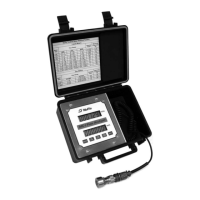
Details the external communications adapter for PC connection.
Steps to install a separately purchased communications adapter.
Steps to mount the Scanner 2000 using a pole-mount kit.
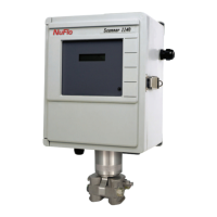
Describes the optional terminal housing for simplifying wiring.
Regulations and warnings for shipping lithium batteries.
Guidelines for disposing of lithium batteries safely.
Useful data for identifying the device on a host network.
Defines FOUNDATION Fieldbus parameters for the Scanner 2000.
Lists parameters for the resource block.
Lists parameters for the transducer block.
Lists parameters for analog input blocks.
Lists error codes and block alarm codes.
Lists control registers and their functions.
Provides unit conversions for XD scale.
| Accuracy | ±1% of reading |
|---|---|
| Response Time | 1 second |
| Operating Temperature | -20 °C to 60 °C |
| Communication Interface | RS-485, Modbus |
| Display | LCD |