73
Scanner
®
2000 microEFM for Foundation™ Fieldbus Section 6
BoardReplacement
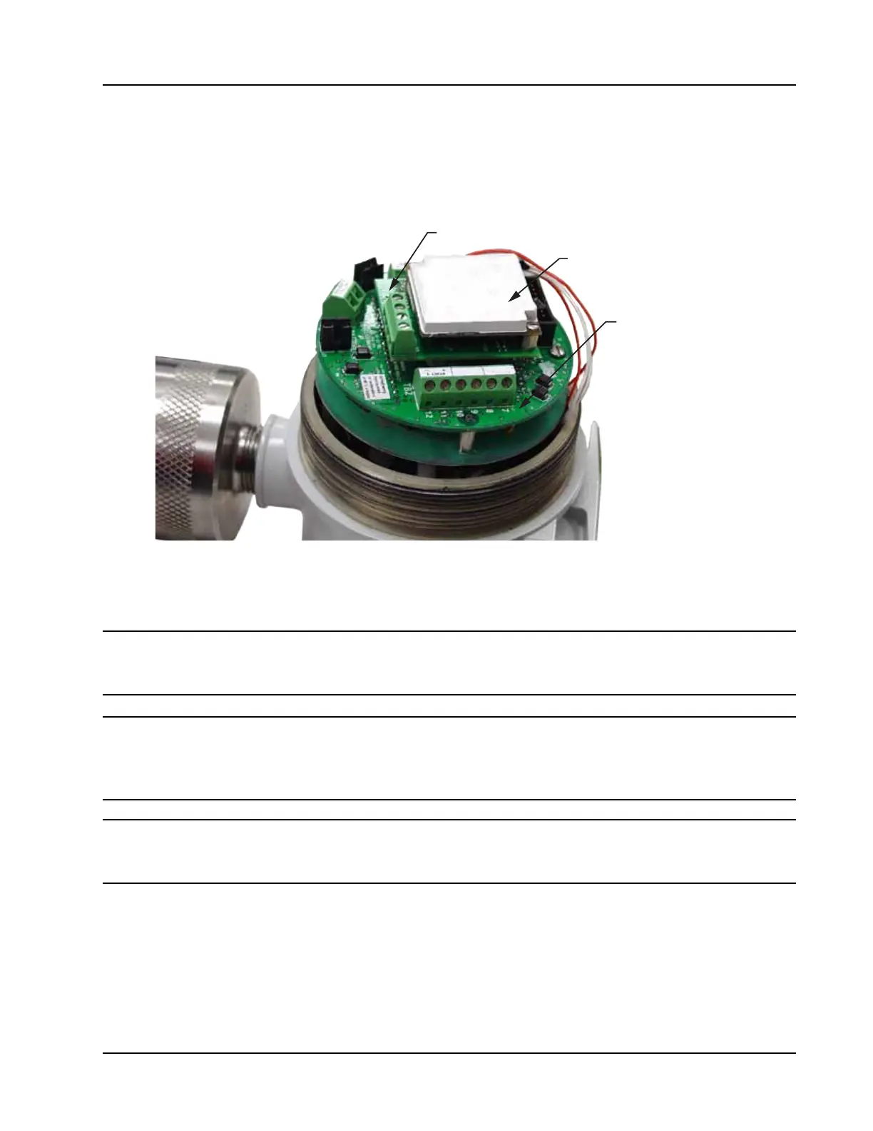
The Scanner 2000 electronic circuitry includes three boards (Figure 6.2). The main board (on bottom of the
board stack when the assembly is removed from the enclosure) is attached to a smaller eldbus interface
board, which is in turn attached to a white potted eldbus module. Only the main board and eldbus interface
board have input/output eld connections.
Fieldbus interface board
Fieldbus module
Main circuit board
Figure 6.2—Circuit board arrangement
Main Board
Important Staticelectricitycandamageacircuitboard.Handlenewboardsonlybytheiredges,
anduseproperanti-statictechniques(suchaswearinganti-staticwriststraportouching
metaltoestablishanearthground)priortohandlingaboard.
Important Ifpossible,downloadthecongurationsettingsandallarchivelogsbeforereplacingthe
circuitboard.PresstheENTER/SAVEkeyonthekeypadbeforedisconnectingthebat-
terytosaveaccumulatedowrunandturbinevolumetotals(grandtotalandcurrentday
total),andenergyandmasstotalstomemory.
Important Theinterfaceboardisattachedsecurelytothemainboardbyastandoffthatisnotvis-
iblewhenallthreeboardsareassembled.Theinterfaceboardcannotberemovedfrom
themainboardwithoutrstremovingthewhitepottedmoduletoaccessthestandoff.
To replace the main board, perform the following steps:
1. Unscrew the cover from the enclosure and set it aside.
2. Using a small standard blade screwdriver, remove the two #4-40 × 7/8” screws located to the right and
left side of the display (Figure 6.1, page 72).



 To Next Page