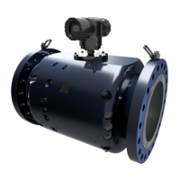
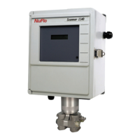
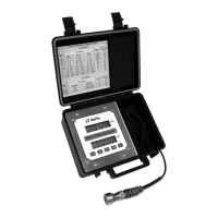
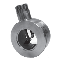
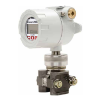
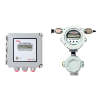
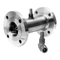
The CALDON SVM 389Ci is a sophisticated, self-verifying ultrasonic flowmeter designed for bidirectional flow measurement, offering high accuracy and unique self-verification capabilities. It employs ultrasonic transit time technology to measure volumetric flow rate and evaluate the uncertainty in the measurement result. The system's advanced signal and data processing ensure robust, high-accuracy measurements and continuous, instantaneous output of uncertainty in terms of volumetric flow rate or a relative percentage value. The SVM 389Ci also totalizes uncertainty values internally and features an automatic fault detection system to verify performance and alert personnel to abnormal operating conditions. For ease of troubleshooting, it provides uncertainty and diagnostic information via Modbus communications and a local display.
Function Description:
The flowmeter consists of two key components: a meter body and a transmitter. The meter body contains 16 pairs of ultrasonic transducers and a temperature sensor (RTD). It is a specially designed flow conduit with multiple pairs of transducer housings positioned to form ultrasonic paths at an angle to the flow direction. The transducers are installed inside these housings, isolated from the fluid and external to the pressure containment. The four primary chordal planes are spaced according to the Gaussian Method of flow integration. Each transducer module uses a piezoelectric element to transmit and receive acoustic energy as ultrasonic pulses.
The CALDON SVM technology utilizes a proven 8-path configuration for primary measurements, with pairs of crossed paths in each of four chordal planes to cancel non-axial velocities and accurately integrate the axial velocity profile. The SVM 389Ci extends this with 16 paths, incorporating three significant features for self-verification: primary (axial velocity) measurement verification per chord, a fifth chordal measurement plane for 4-chord vs. 5-chord estimation of flow profile uncertainty, and a vertical reflective path for detecting entrained gas or contamination.
The G3 transmitter houses the display, providing readouts of flow data, total flow volume, fluid properties, analog input data, alarm indication, fault detection, and diagnostic information. It performs all control and timing for generating and measuring ultrasonic transit times. Specialized proprietary circuit boards within the transmitter handle signal and data processing, achieving high sampling rates, stable ultrasonic signals, and zero drift. These boards are programmed to step through ultrasonic path cycles, measure meter body temperature (for thermal expansion correction), compute flow, communicate with external devices, and generate pulse and analog outputs.
Important Technical Specifications:
- Meter Body: Contains 16 pairs of ultrasonic transducers and an RTD temperature sensor. Utilizes 8-path configuration for primary measurements and 16 paths in total for self-verification.
- Transmitter Material: Standard Aluminum (coated) or Corrosion Resistant Stainless Steel.
- Transmitter Dimensions: 14"x 8" x 6" (152mm x 356 mm x 203 mm).
- Transmitter Net Weight: 15 lb (6.1 kg) for Aluminum (transmitter only), 40 lb (15.9 kg) for Stainless Steel (transmitter only). Total weight with aluminum junction box can exceed 135 lb (61 kg).
- Power Requirements (DC): 24 VDC (18 VDC to 30 VDC), 0.25 A at 24 VDC, 6 W consumption.
- Power Requirements (AC): 120 (60 Hz) / 230 (50 Hz) VAC, 108 VAC to 253 VAC range, 47 Hz to 63 Hz frequency, 0.06 A at 120 VAC / 0.03 A at 230 VAC rated current, 7.3 W nominal consumption.
- Pulse Outputs/Alarm: 0-5 V or 0-12 V pulse/direction outputs (4 total). 5V or 12V for normal operation, 0V for alarm condition (4 total).
- Communications: Up to three RS485 ports (2 Wire - Modbus RTU), Ethernet port (Copper (1 x RJ45 and TB2) or Fiber) with Modbus TCPIP, Optional HART channel (operates on second analog output).
- Analog Outputs (2 total): 4-20 mA (max load 650 Ohms).
- Analog Inputs (3 total): 4-20 mA (Meter body RTD is standard).
- Environment Requirements: Storage Temperature -58°F (-50°C) to 185°F (85°C), Operating Temperature -58°F (-50°C) to 158°F (70°C).
- Altitude: Up to 5000 meters for DC applications, 2000 meters for AC applications (contact Sensia for higher elevations).
- Approvals: Available with Class/Div, ATEX Exdb IIB + H2, ATEX Exdb IIC, IECEX Exdb IIB + H2, or IECEX Exdb IIC approvals.
- K-Factors: Standard K-Factors for various pipe sizes (DN 300 to 900) are provided, configurable by the user.
Usage Features:
- Self-Verification: Continuous calculation and output of measurement uncertainty, along with fault detection.
- Diagnostic Information: Easy-to-interpret uncertainty and diagnostic data via Modbus communications and local display. More detailed data available via CALDON USM Advisor software.
- Bidirectional Flow Measurement: Capable of measuring flow in both directions.
- Temperature Compensation: Automatic compensation for pipe thermal expansion and contraction using an integrated meter body temperature measurement (ISO17089 compliant). Can be disabled if external flow computer compensation is preferred.
- Display: 400x240 pixel LCD showing flow rate, totalized flow, fluid properties, and diagnostics data. Parameters scroll independently in a continuous loop.
- Alarm Conditions: Automatic fault detection system alerts personnel to abnormal operating conditions, verifying transducer and transmitter electronics performance.
- Output Test Mode: Used for field testing or verification checks of analog and pulse outputs, ideally with USM Advisor software.
Maintenance Features:
- General Inspections: Bi-annual or site-guideline-based inspections of transmitter enclosure and meter body for structural damage, dust, dirt, and gasket integrity.
- Internal Electronics Inspection: Requires ESD protective wrist strap. Inspect cable entry points, cable connections, and all internal connections/terminals for tightness and corrosion.
- Transmitter Troubleshooting: LEDs indicate power and operation status. Troubleshooting steps include checking power supply, setup file integrity, and power supply voltages on MXR and CTC boards.
- Circuit Board Replacement: Instructions provided for replacing Input/Output and Power Supply (IOP) board, Control and Timing Card (CTC) and Display, and Multiplexer, Transmitter and Receiver (MXR) board.
- Fuse Replacement: Instructions for replacing the F25 fuse on the IOP board.
- Transducer Installation: Step-by-step procedure for replacing transducers, including removal of tamper evident seals, access covers, and transducer internals. Requires technical guidance from Sensia.
- Analog Input Verification: Verification of analog inputs (temperature, pressure, density) scaled linearly to convert 4-20 mA to engineering units.
- Analog Output and Pulse Output Verification: Verification of 4-20 mA analog outputs and 0-5V or 0-12V pulse outputs using force output functions in USM Advisor software.
- Reprogramming the Transmitter: Procedure for reprogramming the transmitter with the appropriate configuration file using USM Advisor software if the processor fails or requires replacement.
- Metrological Seals: Design includes seals to control programming of the transmitter or alterations to the meter body, with a switch on the CTC board for write protection. Tamper-evident seals on IOP and transducer cover fasteners.
- Recommended Spare Parts: List includes transducers, transducer grease, display board, CTC board, IOP board, MXR board, MXR daughter board, and transducer interface board. Functional test of printed circuit boards recommended every 5 years.

 Need help?
 General


 To Next Page