9
Model 7000 Series Turbine Flowmeter Section 2
BestPracticesforInstallation
Before installing a Barton turbine owmeter, read the following best practices
in their entirety.
Filtration
All meters should be installed with upstream ltration to isolate the meter
from damage from foreign objects in the piping system. See the Barton 7000
Series product data sheet for recommended ltration size. Cameron offers
start-up screens as an optional accessory to prevent damage from foreign
objects.
Avoid the use of Teon
®
tape on body threads. Strands can enter the ow-
stream and collect on the rotor, causing measurement error.
All meters should be isolated from gas or liquid “slugs” which can cause
damage by over-speed and water hammer.
Electrical Installation
Consider the process operating temperature when selecting the type and
location of electric tting and instrument components. Heat conducted and
radiated from the turbine can damage wiring, connectors, electrical housing
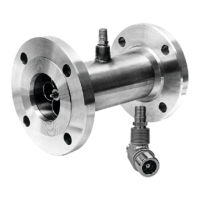
and circuit boards. The meter can be installed so that the pickup coil is in any
plane. Avoid orienting the pickup coil in a 12 o'clock position in applications
with elevated temperatures.
Where possible, minimize the length of signal transmission cables from the
pickup. The signal from the turbine is a low-voltage AC sine wave that can be
as low as 30mV peak-to-peak. Electrical noise on the wires will cause false
counts on the readout instruments. Direct-mounting a totalizer or preampli-
er is preferred. If this is not possible, ensure that the signal cable is not near
power cables, other signal cables, or routed where electrical noise may inter-
fere with signal transmission.
Follow common wiring installation practices, using quality cable (twisted
pair, shielded with ground wire).
Flowmeter Position
Barton turbine owmeters are calibrated in a horizontal position. Therefore,
the best correlation of calibration occurs when the meter is operated in this
plane. However, the meter will operate satisfactorily in any position.

 Loading...