www.sensirion.com Version 0.93 – D1 – December 2018 2/19
1 Digital interface description
The SCD30 digital interface is compatible with the I2C protocol and the Modbus protocol. For selecting Modbus protocol, the
SEL pin needs to be pulled to VDD Voltage. Please refer to datasheet.
1.1 I2C Protocol
Maximal I2C speed is 100 kHz and the master has to support clock stretching. Clock stretching period in write- and read-
frames is 12 ms, however, due to internal calibration processes a maximal clock stretching of 150 ms may occur once per day.
For detailed information to the I2C protocol, refer to NXP I2C-bus specification
. SCD30 does not support repeated start
condition. Clock stretching is necessary to start the microcontroller and might occur before every ACK. I2C master clock
stretching needs to be implemented according to the NXP specification. The boot-up time is < 2 s.
1.1.1 I2C Address
After power-up of the sensor, the I2C address of the prototype module is set to the address 0x61.
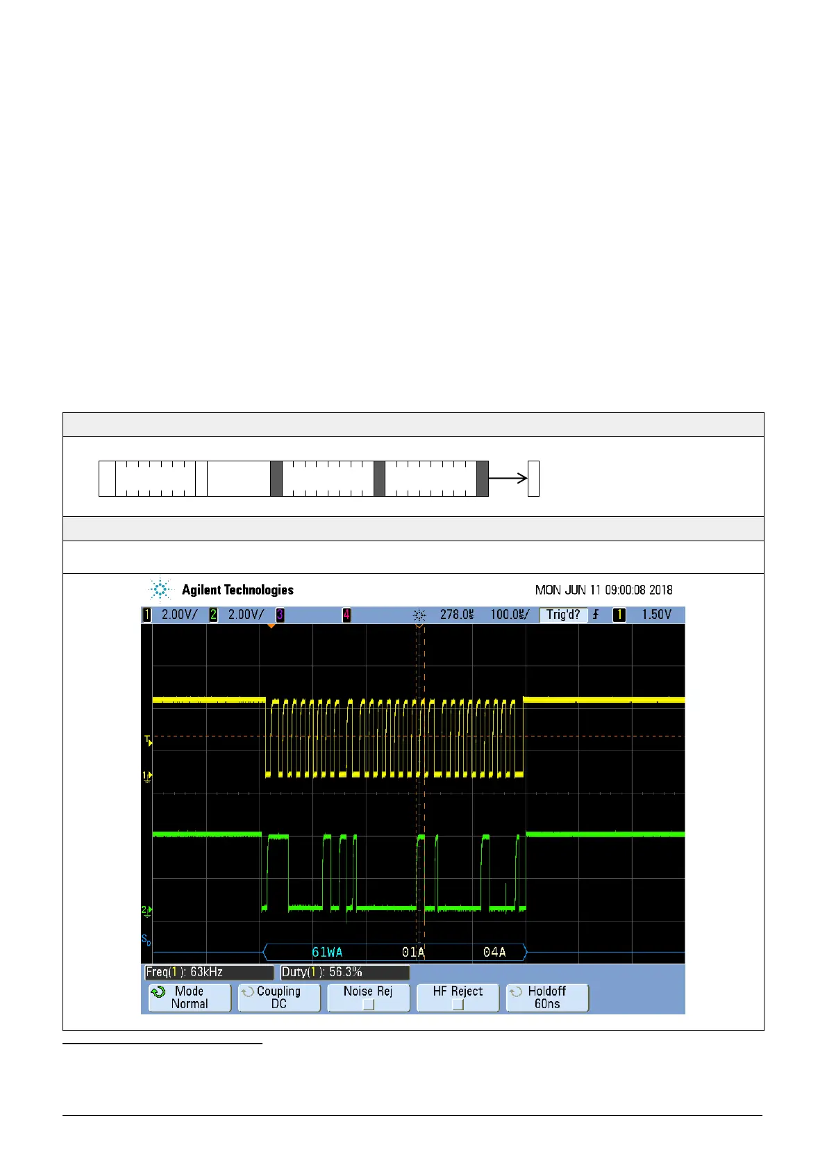
1.1.2 I2C Sequence
The commands issued by the I2C master are 16 bit with an optional parameter. Data sent to the master is protected by a
CRC. This also applies to data arguments sent to the sensor, please see chapter 1.1.3 for CRC checksum calculation. 2 byte
data sent from or received by the sensor is always succeeded with an 8 bit CRC. Examples are shown below.
I2C write 16bit command without arguments
Example: Stop measurements 0x0104
START 0xC2 0x01 0x04 STOP
(Red: Write Header; Blue: Read Header; Black: Data; Green: CRC; Start Condition: START; Stop Condition: STOP)
http://www.nxp.com/documents/user_manual/UM10204.pdf