-7-
3 Wiring
3.1 Wiring of alarm contact output
()Contact capacity is specified with AC 250V , 3A resistance load, COS φ=1.0
When switching the load more than this, use power relay to fit the load connected.
()
Before wiring the load, check on which control action upper limit/lower limit
ALM1, ARM2 are set.
Please pay attention in wiring load to it that COM-B contact is ON when
instrument power is OFF.
()This PE-8E has 2 channels of alarm contact output; ALM1 and ALM2 1c contact output
Control action of both ALM1 and ALM2 can be set upper limit action or lower limit action by
DIP. Switches.
At delivery to you, PE-8E is initially set as follows;
()At delivery to you; ALM1 Upper Limit Action H
()ALM2 Lower Limit Action L
The initial set content shows when the instrument is powered ON.
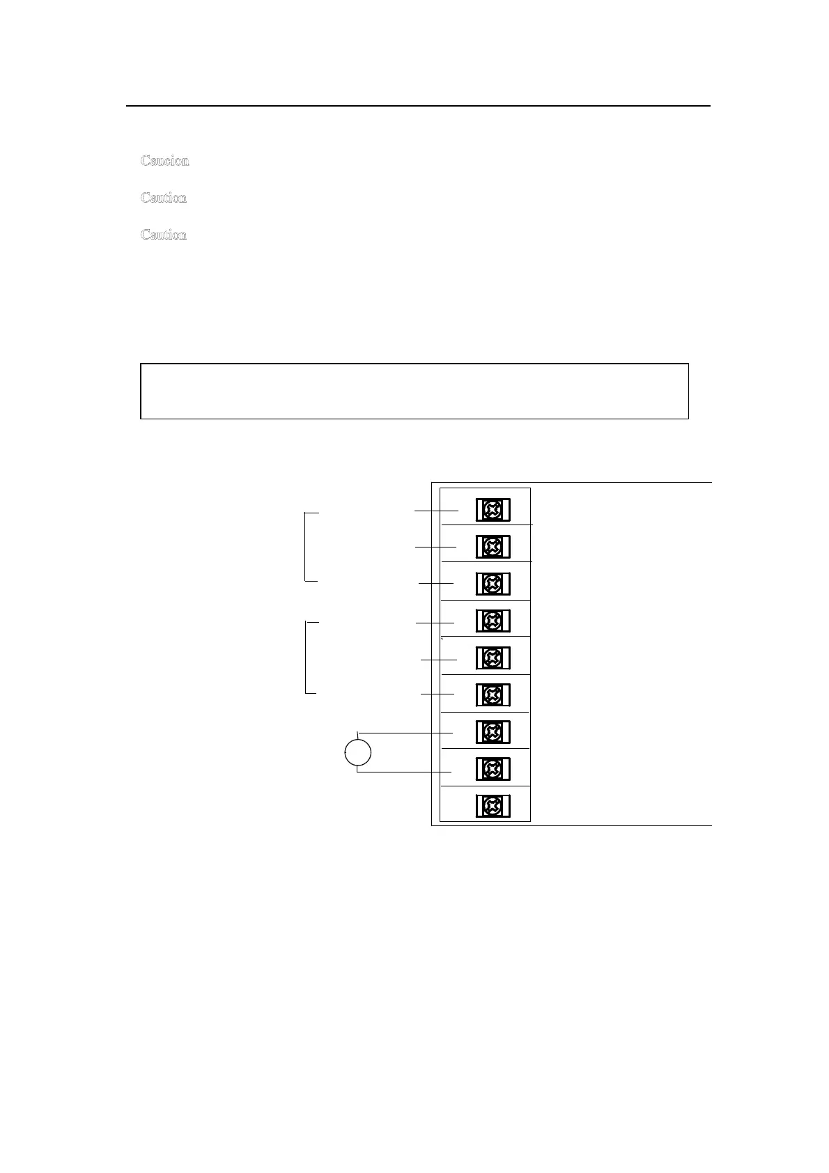
ALM 1 COM 1
control contact output
capacity; AC250V,3A a CONTACT 2
()load resistance
bCONTACT 3
COM 4
ALM 2
control contact output a CONTACT 5
capacity;AC250V,3A
bCONTACT 6
7
Power Source ~
AC90~250V 8
50/60Hz
GND 9
Ground
 Loading...